The DUT Performance Functional Verification is based on a bench test software that does not account for EMC specific considerations and is normally performed prior and following each EMC test method.
Using the same Activation & Monitoring Method and Pass/Fail Criteria for ENV and EMC is not practical. DUT’s functions must be grouped in “operating modes” that are in line with the scope of EMC Test Method. When assessing the level of RF emissions we want the DUT to exhibit the highest level of noise possible as in vehicle. During RF Immunity evaluation we expect the following from a good activation/monitoring software:
- Capability to activate and have realistic data traffic on all I/O lines as well as individual I/O lines.
- Electrical Transients or RF coupled in supply voltage and I/O lines may not always trigger repeatable anomalies. Therefore we need a visible flag/indicator to immediately stop the actual EMC test method process for anomaly thresholding (e.g. level vs frequency). As we reduce applied stress level the DUT’s behavior may change, then at some point the anomaly should disappear.
- The same DUT operating mode may be feasible for one or more EMC test methods but definitely not for the entire test list. We need capability to configure what functions belong to each operating mode including live monitoring method. Log files are not useful during test, we still need them following the test for troublesooting.
- All functions must resemble vehicle intent usage. Not all I/O lines will be active simultaneously in vehicle. Therefore do not use unrealistic I/O cables scenarios to facilitate testing since this can generate false current loops and other issues.
- The functions used by DUT activation & Monitoring Software are not meant to assess complaince to USB, E-Net, LVDS standards.
Keep in your mind that:
- Electrical Transients on supply lines can hard reset the MCU (e.g. dips/dropouts). Is there a test in your monitoring software that captures such condition? Any other anomaly is not relevant once a hard reset occurs.
- Do you have a function to verify that there is no memory loss following inadvertent hard/soft reset?
- The RF can be coupled in both supply lines and I/O lines resulting in data traffic interruptions leading to a soft reset. Is there a monitoring function to capture such event?
- If CAN bus is used in a design I would consider at minimum two critical errors: CAN BUSOFF & DTC SET. What we normally use is a pass fail criteria that can be adjusted such that is possible to determine if the anomaly occurs with every data transmission attempt or it happens only each 100/1000 attempts.
DUT support software
Do not waste time/money to tweak operating modes during EMC validations. In many EMC labs the cost for one hour of ALSE chamber is $500 regardless to how you spend this time. The operating mode must be pre-selected, yet adjustable if needed during troubleshooting. The "anomaly found" visual indicator is used by EMC test operator to stop the actual EMC test software. If we have a time stamp in log files, there is no need to stop the activation/monitoring support software.
DUT Activation Dwell Time
All functions within the same operating mode must be completed and repeated every 2 seconds. We call these 2 seconds Dwell Time, and it can make a huge difference in test duration and cost. For a 2-second dwell time and only one Operating Mode you can expect RF Immunity in ALSE chamber to last 4-5 days (one shift). For a 4-second dwell time it may last practically 8-9 days and so on. Bottom line, if the initialization of Load Simulator or DUT is time consuming it will cost a fortune to re-initialize following each incident/anomaly. Hard/soft reset must always be the last resort to resume operation. The goal is to minimize the number of operating modes and DUT orientations.
Types of DUT support software
- Load Simulator EMC support testing software with specific sections for each Operating Mode.
- Load Simulator Functional/Parametric verification testing done before and after each Test Method.
- Full DUT Functional/Parametric testing before and after full EMC validation that is not typically done using the EMC Load Simulator but rather EOL like testers.
DUT Operating Mode
Ideally is to include in Operating Modes only those DUT functions that are active while driving the vehicle. Functions used for diagnostics at the car dealer shop are not relevant. The worst case scenario is when vehicle is in Run Mode (speed >0) but we also have to simulate the Standby Mode (speed = 0) and Sleep Mode (current consumption < 1 mA).
Christian Rosu, Jan 12, 2021
22. December 2020 06:33 by Christian in
The Intermodulation Interference (IM) occurs when the two transmitters are in close proximity and their signals mix in one or both of their final amplifiers. This generates unwanted signals at the sum and difference of the original frequency transmissions.
Passive Intermodulation (PIM) is an intermodulation distortion that occurs in linear devices (e.g. cables, connectors and antennas) as unwanted signals created by the mixing of two or more strong RF signals due to a loose or corroded connector, or nearby rust.
Antenna factor when properly applied to a field strength meter reading yields:
- electric field intensity (V/m)
- magnetic field intensity (A/m).
The field intensity in the far-field radiation pattern of an antenna:
- Is proportional to the square root of the effective radiated power. Increasing the effective radiated power four times , the field intensity will be doubled.
- Is direct proportional to antenna current. If the far-field intensity in the far-field antenna pattern is doubled the antenna current will increase 2 times.
16. December 2020 15:52 by Christian in
EMC/EMI, Shielding Shielded enclosure example:
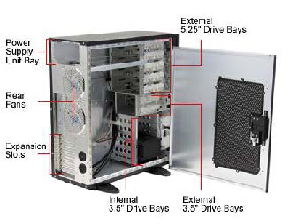
Shielded enclosure connector types:
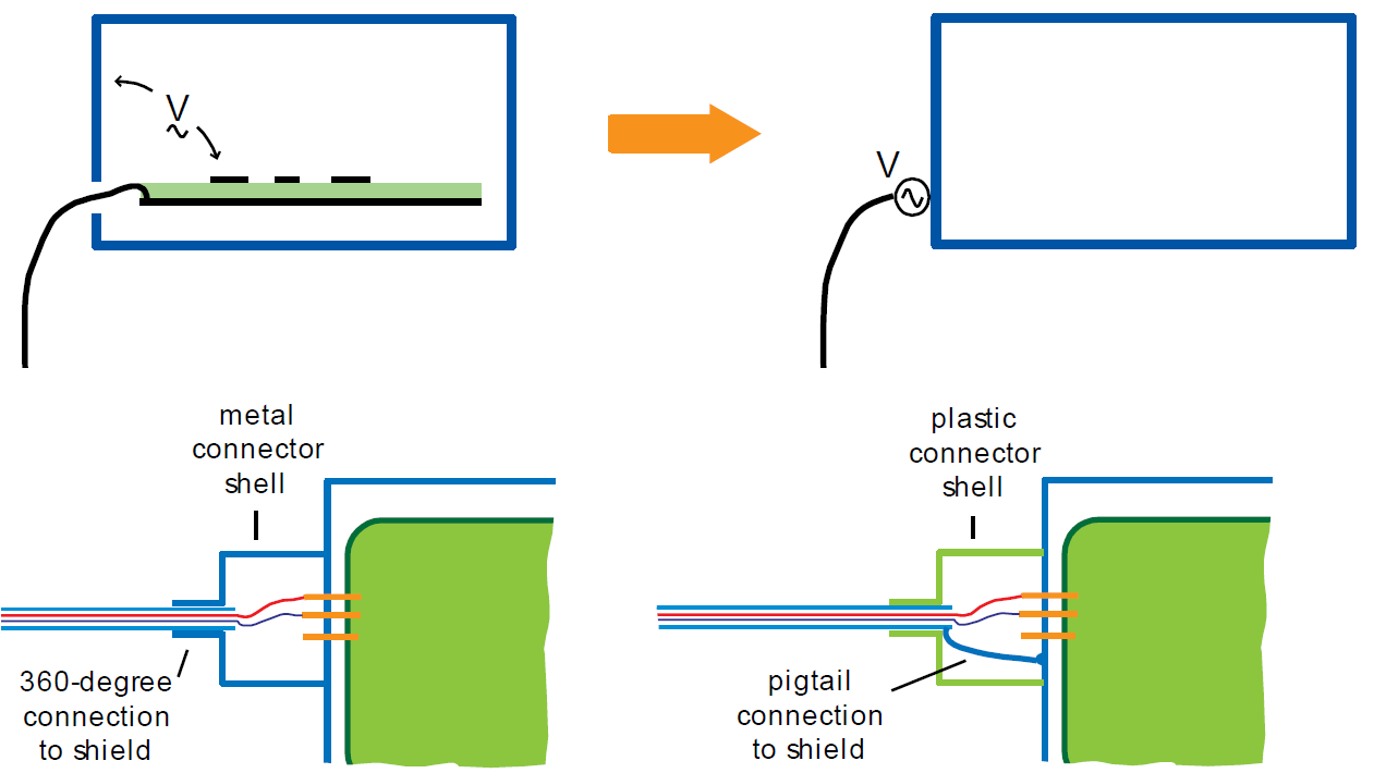
See Troubleshooting RF Noise and Fixing Ground Loops
Shielded cable types:
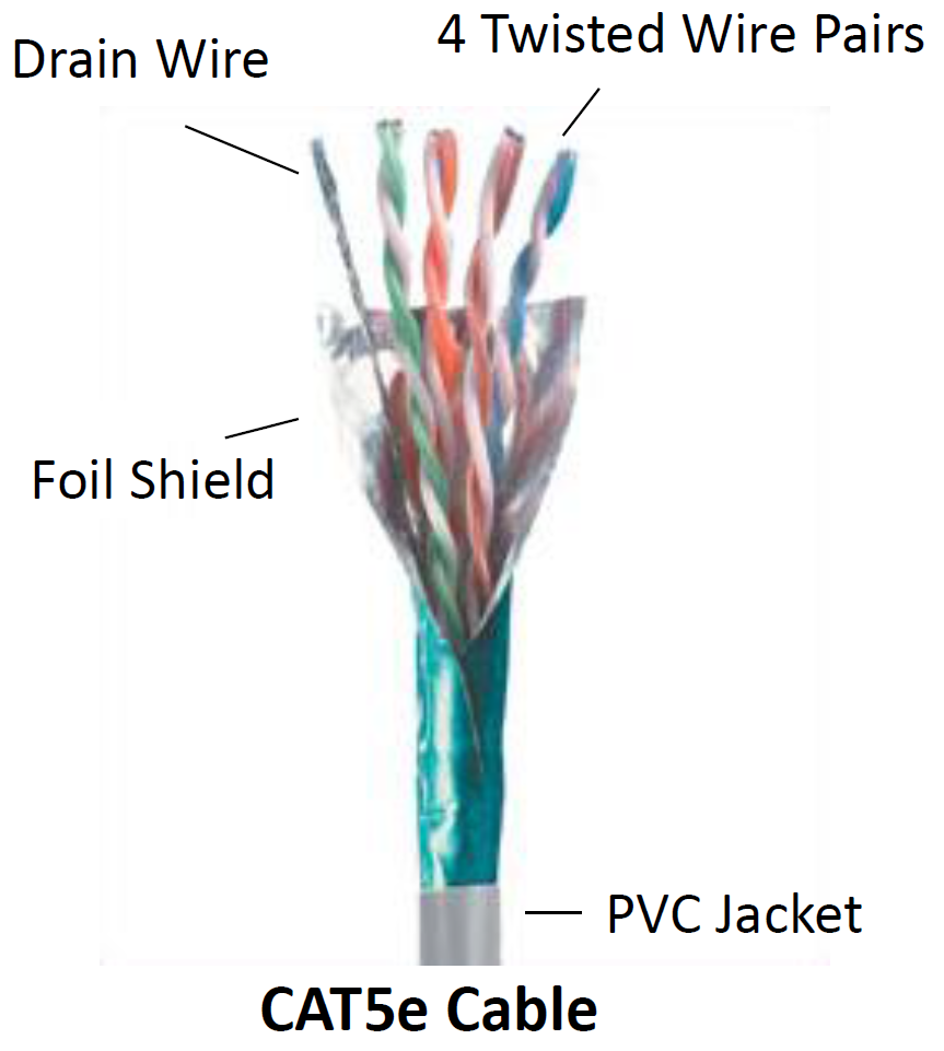
- Foil provides high-frequency shielding.
- Drain wire carries most of the low- frequency current.
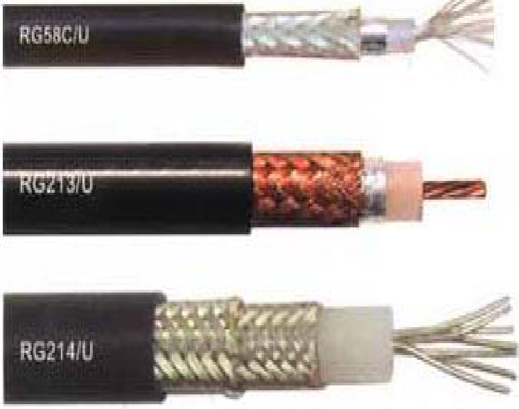
- Foil provides high-frequency shielding.
- Braid carries high-currents.
Why Cable Shielding?
- Serves different purposes in different applications.
- Sometimes carries intentional signal currents. This is an example of self-shielding.
- May prevent coupling of external electric or magnetic fields to signals carried by wires in the cable.
- Beware of transfer impedance data. It should only be used to compare similar cables for a similar application measured with the same test set-up.
Summary of Main Points:
- Electric field shielding, magnetic field shielding, cable shielding and shielded enclosures are very different concepts requiring different materials and
approaches. - It is important to be understand the coupling mechanism you are attempting to attenuated before coming up with a shielding strategy.
- Electric field shields terminate or redirect electric fields. Where they are “grounded” is often critical.
- Magnetic field shields redirect the magnetic field. Magnetic fields cannot be terminated.
- Low frequency (<kHz) magnetic fields must be redirected with high permeability materials.
- High frequency magnetic fields can be redirected with good conductors of sufficient thickness.
- Shields and imperfect shielded enclosures can significantly increase radiated emissions.
- Shields reduce radiated emissions by disrupting the coupling from near-field sources and the “antennas” in a system.
- In the near field, shields are either electric or magnetic field shields that redirect high-frequency current flow.
For a radio (transmitter or receiver) to deliver power to an antenna, the impedance of the radio and transmission line must be well matched to the antenna's impedance.
The parameter VSWR is a measure that numerically describes how well the antenna impedance is matched to the radio or transmission line it is connected to.
The voltage component of a standing wave in a uniform transmission line consists of the
- forward wave (with complex amplitude
 ) superimposed on the
 - reflected wave (with complex amplitude
 ).
).
A wave is partly reflected when a transmission line is terminated with other than an impedance equal to its characteristic impedance.
The reflection coefficient  can be defined as:
= Vr / Vf
is a complex number that describes both the magnitude and the phase shift of the reflection. The simplest cases with measured at the load are:
-
 complete negative reflection, when the line is short-circuited,
 -
 no reflection, when the line is perfectly matched,
 -
 complete positive reflection, when the line is open-circuited.
The voltage standing wave ratio is then:
See Tutorials