The goal is to EMC validate DUT's Hardware Design assuming that DUT's Software was developed to serve the DUT's Hardware. Following a successful EMC validation, the DUT software may be subject to multipe updates and upgrades to serve the original hardware design w/o altering the outcome of overall product EMC validation.
DUT's software is used to exercise and monitor I/O lines and functions. The use of DUT production software should not be mandatory since may not be finalized prior to validation. The use of specialized DUT software is recommended since the production software may not be efficient enough to otimize the EMC testing time. The use of specialized DUT software is allowed provided that:
1) SW diagnostic timers are set to minimum detection values such that during the maximum 2-second RF exposure time all DUT response error flags are being captured and reported. Using production intent software would extend the DUT activation dwell time beyond 10 seconds such that long duation functions and/or sequential activation of various functions becomes possible.
2) DUT's state and fault conditions are reported directly via communication bus or indirectly via cyclying the outputs (e.g. changes to PWM duty cycle, monitoring LED flash rate, inadvertent status change).
3) DUT monitored data, I/O status values, analog input voltages, operating state are queried via parameter requests to ensure bi-directional communication during RF Immunity. Monitoring functional status via DUT scheduled or periodic broadcast messges is not recommended.
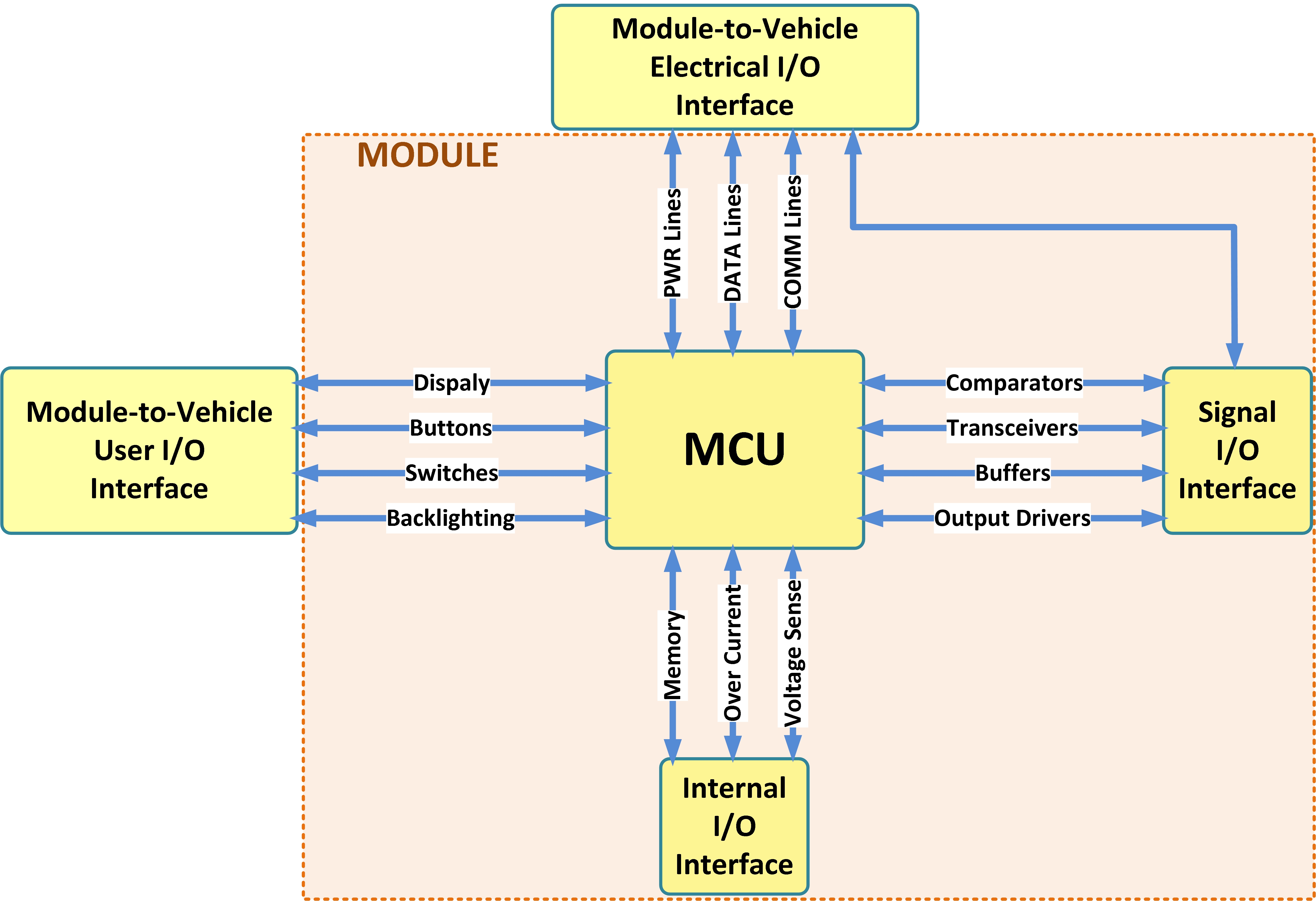
Module to Vehicle Interface Connector and User Interface I/O
Analog Inputs are set nominally to mid-range values and reported:
- directly via communication bus
- indirectly via cyclying the outputs (e.g. changes to PWM duty cycle, monitoring LED flash rate, inadvertent status change)
Analog Outputs are set nominally to mid-range values and reported:
- directly via Fiber Optic system
- indirectly via loop back method (e.g. monitoring the simulated load using a DUT input)
Digital Inputs are dynalically cycled "on-off-on" during RF exposure and their state reported:
- directly via communication bus
- indirectly via cyclying the outputs (e.g. changes to PWM duty cycle, monitoring LED flash rate, inadvertent status change).
Digital Outputs are dynamically cycled "on-off-on" during RF exposure and their state reported:
- directly via Fiber Optic system
- indirectly via loop back method (e.g. monitoring the simulated load using a DUT input)
Communication Bus message loading
- The analog properties of the bus electrical signal (e.g. Vdominant, Vrecessive, etc. must be validated during RF immunity.
- This may require special software to decrease the data rate to be within the bandwidth limitations of analog fiber-optic transmitters.
RF I/O (Telematics, GPS, Wi-Fi, Bluetooth, RKE, TPMS) must be activated during EMC testing:
- Received signals must be set to 3 dB above specified minimum sensitivity level.
- The RF level is to be established with DUT installed in test chamber.
- Bit Error Rate (BER) is the preferred metric with an acceptance threshold set by RF device specifications.
- BER must be monitored directly through the communication bus via parameter requests (never via scheduled, or periodic, broadcast messages).
- Transmitted signals must be monitored by an appropriate RF receiver, again monitoring BER, acceptable threshold set by RF device specifications.
MCU Connector “Internal” I/O
For such internal I/O (not connected to Vehicle I/O connector), the monitoring must be done via communication bus data or via indirect methods. Direct monitoring using attachments leads to external monitoring devices is not allowed.
- MCU Analog Input is set to nominal operating value/condition for the specified test mode with the value reported either directly via the DUT communications bus or, indirectly through the DUT monitoring the input and changing the state of an output in a known, pre-determined manner. These functions are based on internal Printed Circuit Board (PCB) operating conditions and are not expected to
be controlled or changed during testing; it is not necessary to force a mid-value for these inputs as with vehicle harness interface I/O. - Digital Input - Non-dynamic (Steady State I/O). Examples include feedback fault indication, over/under current monitoring via discrete comparator circuit, etc. The input is set to the nominal operating value/condition for the specified test mode with the value reported either directly via the DUT communications bus or, indirectly through the DUT monitoring the input and establishing the state of an output in a known, pre-determined manner. Not to include reset, address/data lines and communication between the microprocessor and electronically erasable programmable read-only memory (EEPROM), etc.
- Digital State Input - Dynamic Cycling I/O. Requires state change between asserted to non-asserted back to asserted states during radiated immunity RF “on” exposure, reported directly by communication or indicate indirectly via output state change by detected input. Reset, address/data lines and communication between the micro and EEPROM are not included. The following MCU I/O types do not require direct monitoring since are indirectly monitored by the inherent operation of the device: Discrete outputs, Analog outputs, Internal communication bus.
Christian Rosu
Reference: Automotive OEM EMC specs