In automotive applications the LIN bus is used as communication bus for various functions:
- Steering wheel: Cruise control, wiper, climate control, radio
- Comfort: Sensors for temperature, sun roof, light, humidity
- Powertrain: Sensors for position, speed, pressure
- Engine: Small motors, cooling fan motors
- Air condition: Motors, control panel (AC is often complex)
- Door: Side mirrors, windows, seat control, locks
- Seats: Position motors, pressure sensors
- Other: Window wipers, rain sensors, headlights, airflow
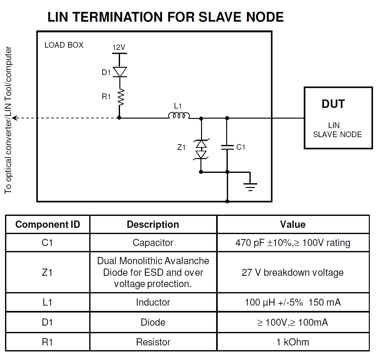
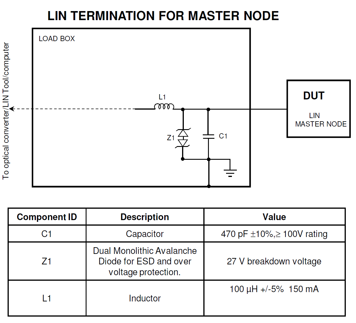
A master node loops through each of the slave nodes, sending a request for information - and each slave responds with data when polled. The data bytes contain LIN bus signals (in raw form).
For EMC component level testing purpose, the LIN bus termination must be properly terminated to simulate vehicle loading scenario.
Christian Rosu, Nov 10, 2021
The latest revision of CISPR 25 is looking into various types of Artificial Networks used in today's automotive EMC.
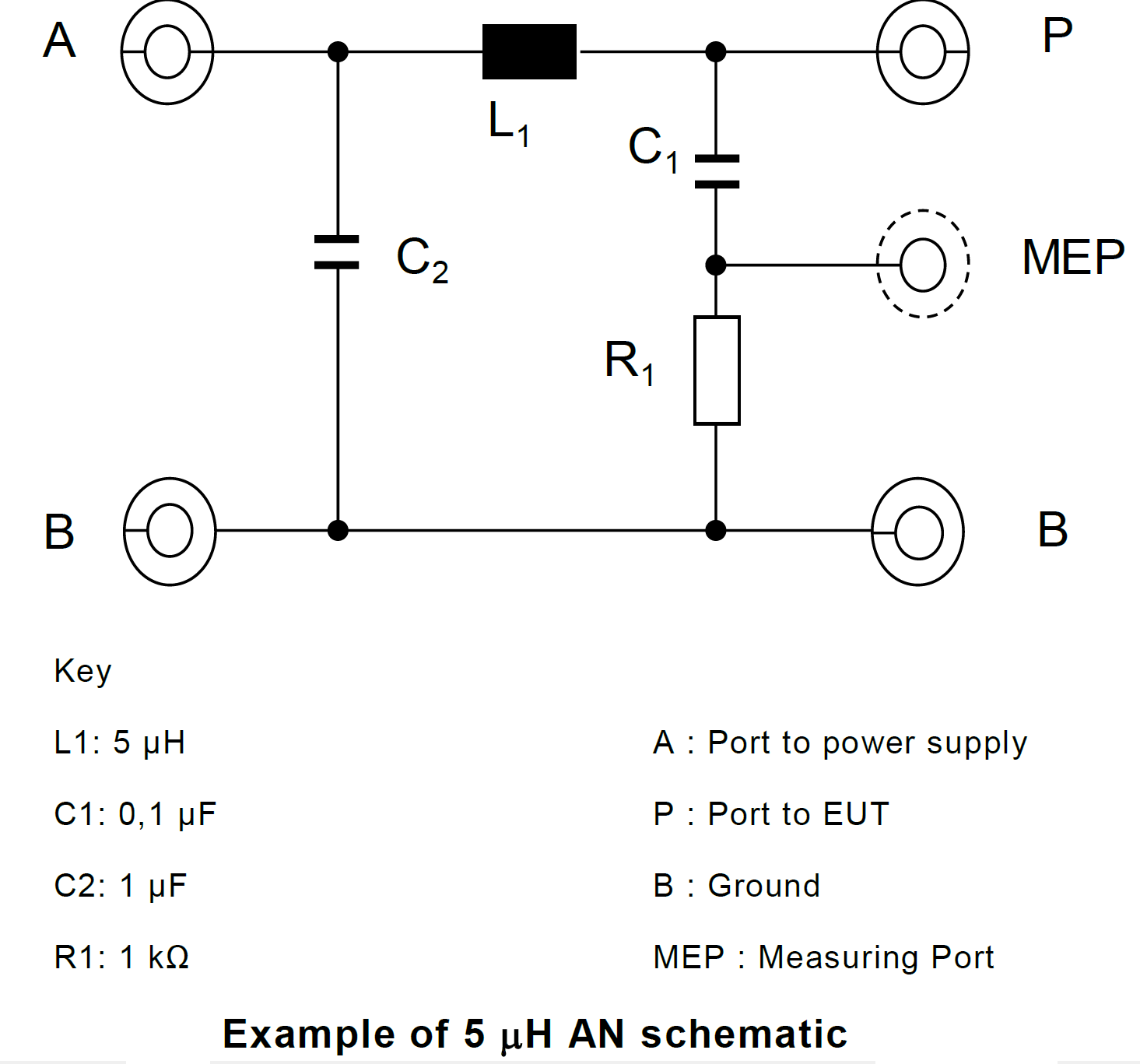
1. Artificial Network (AN): used for LV power supplies;
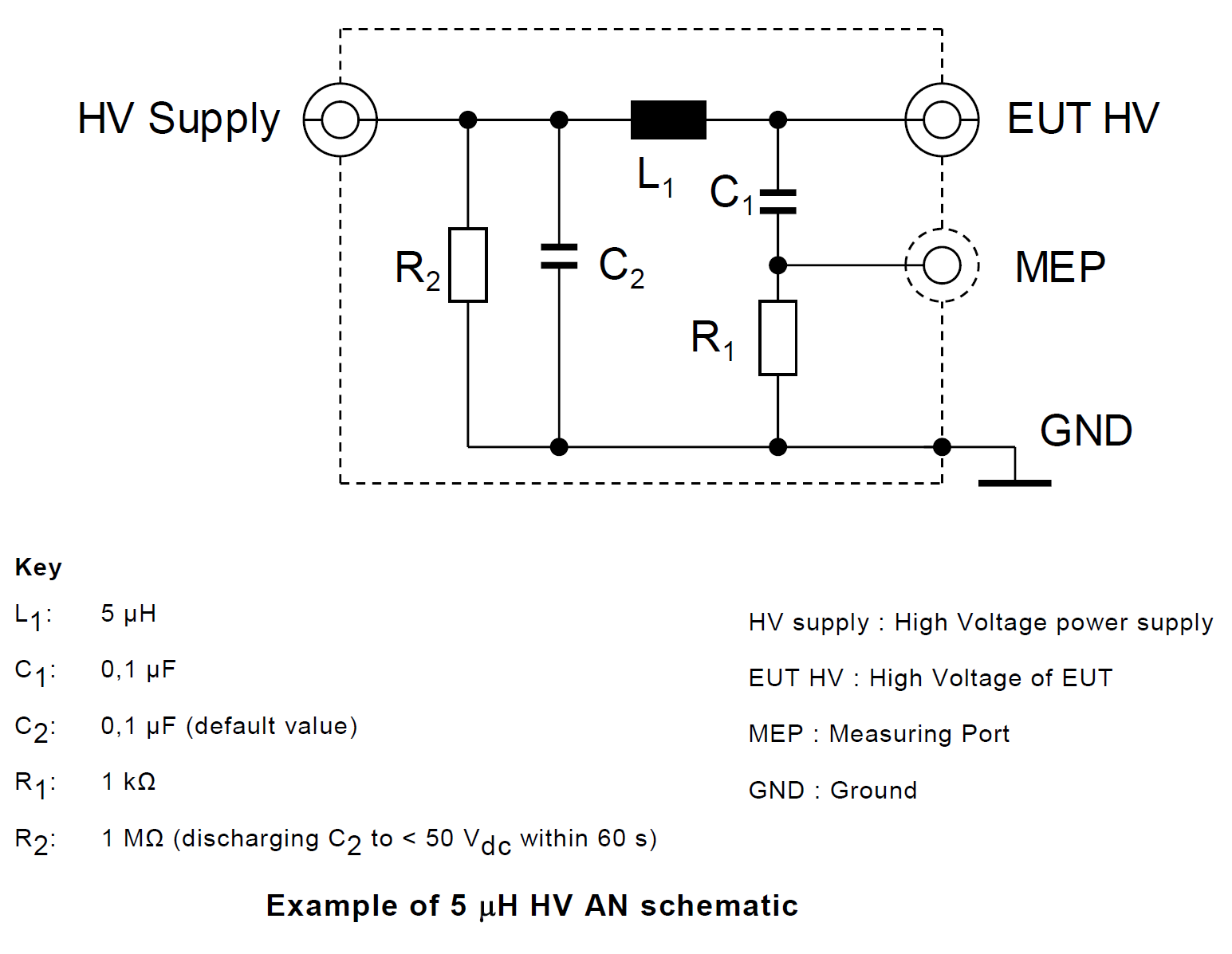
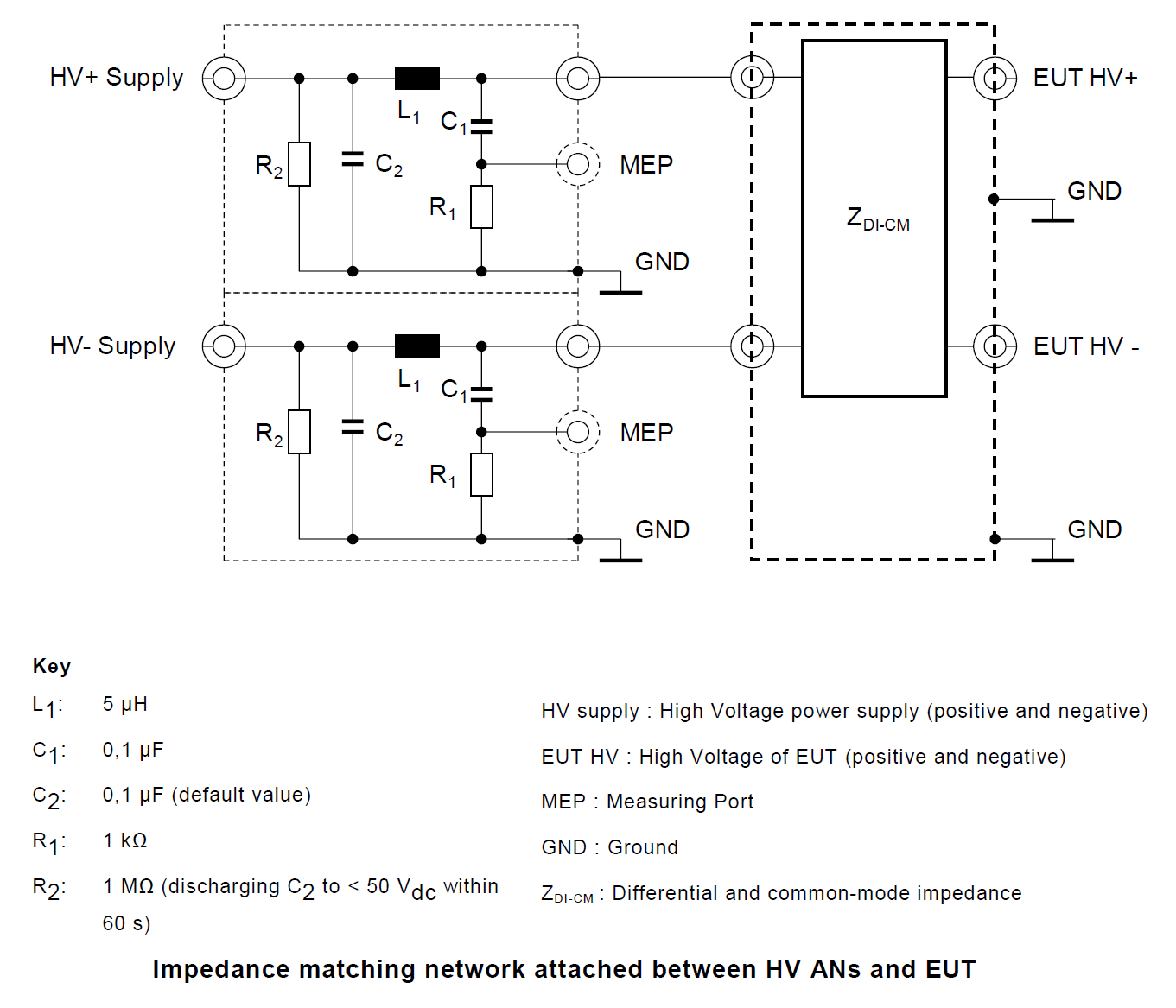
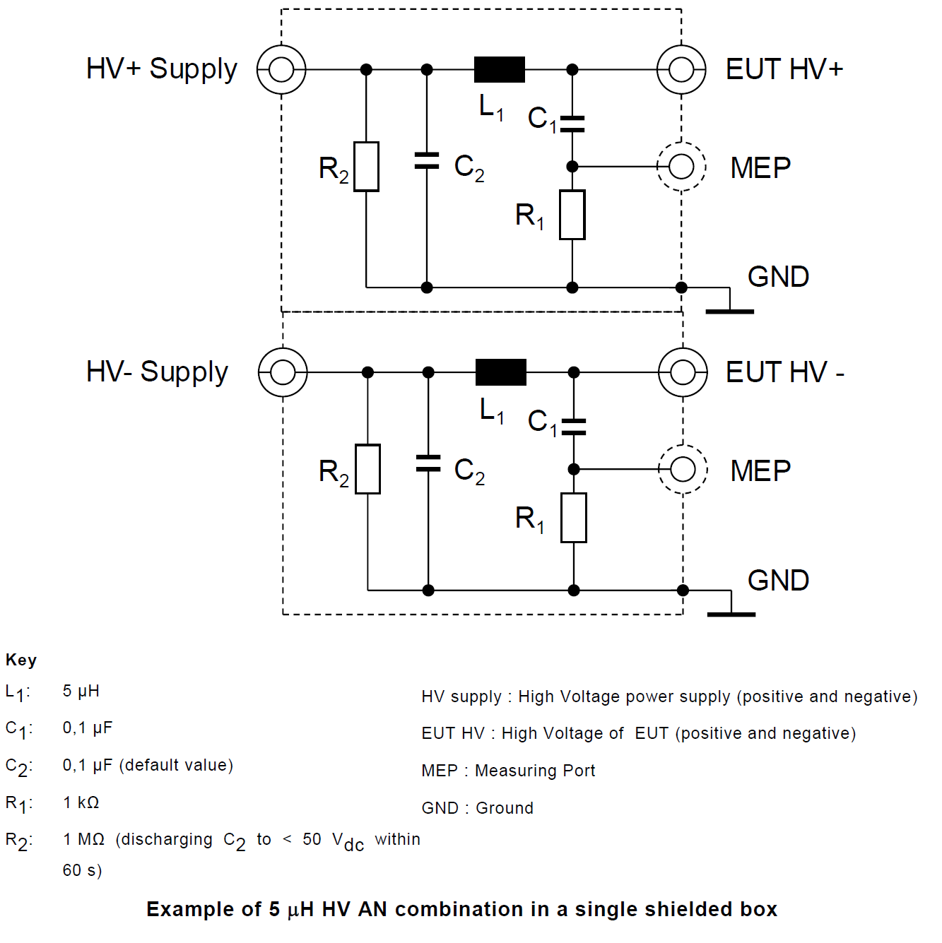
2. High Voltage Artificial Network (HV-AN): used for high voltage d.c. power supplies;
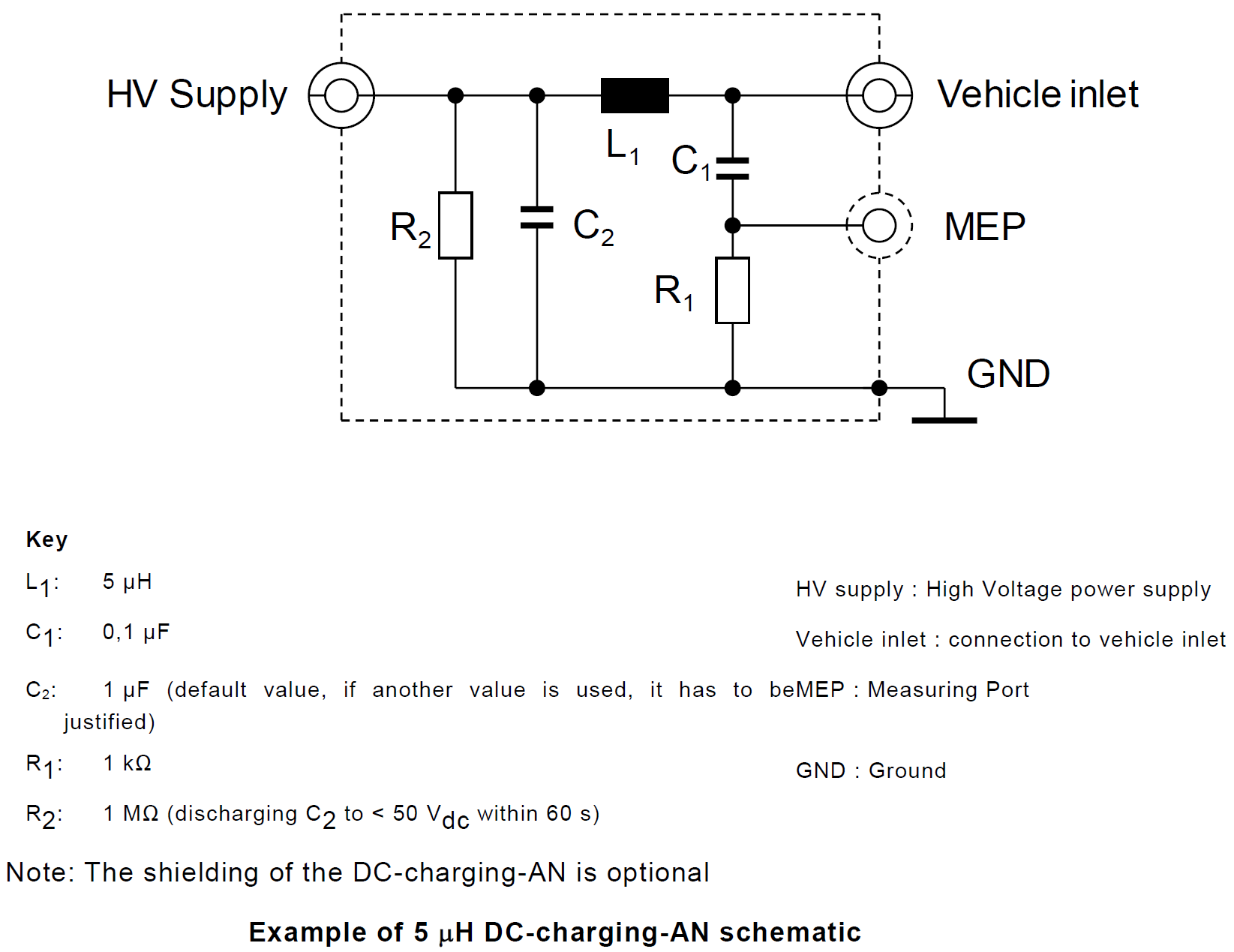
3. Direct Current charging Artificial Network (DC-charging-AN): used for d.c. power supplies;
4. Artificial Mains Network (AMN): used for a.c. power mains;
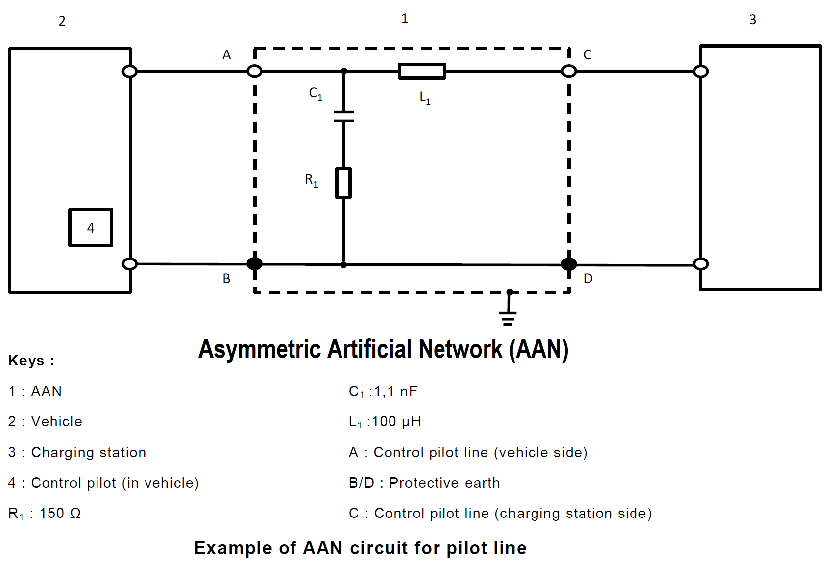
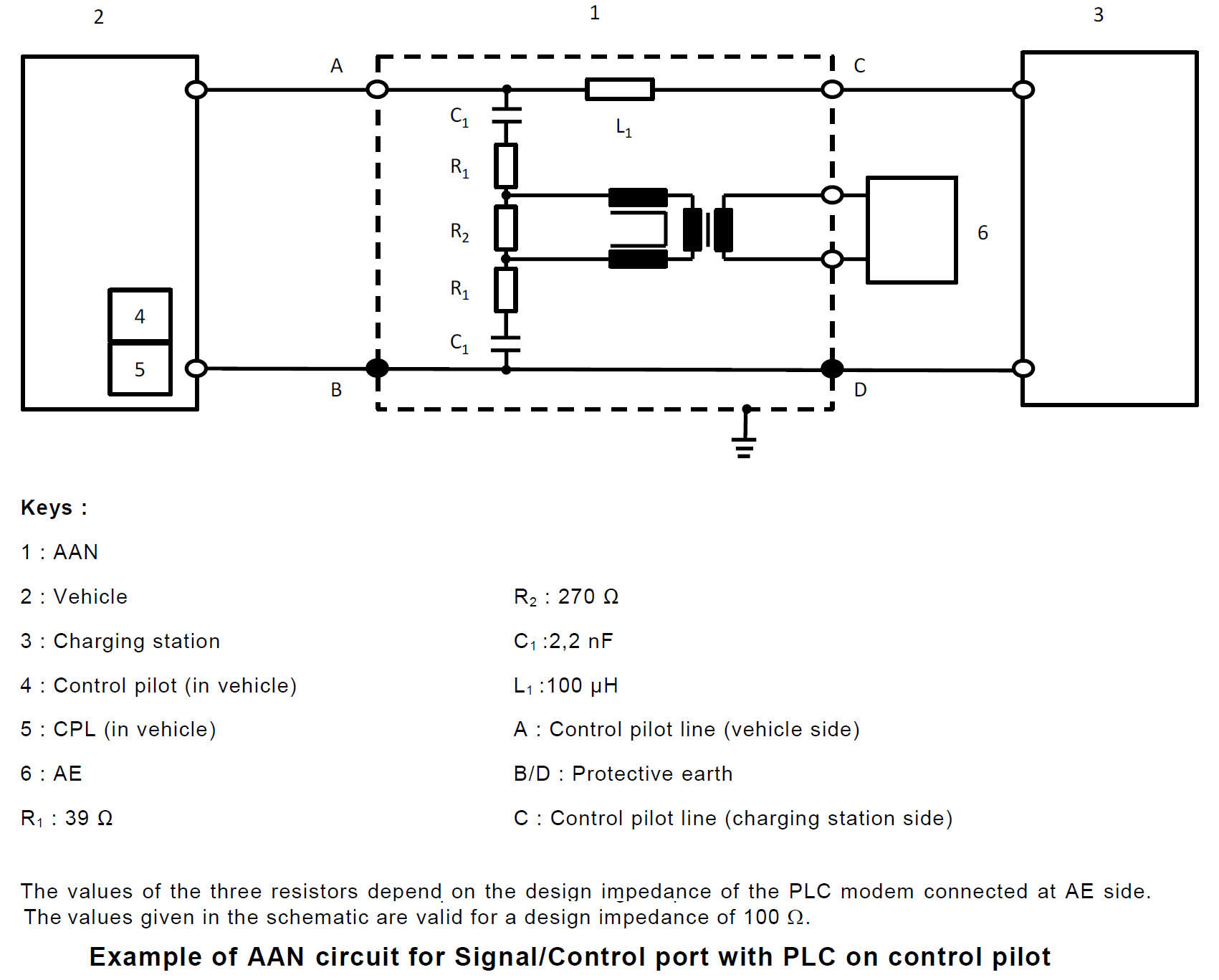
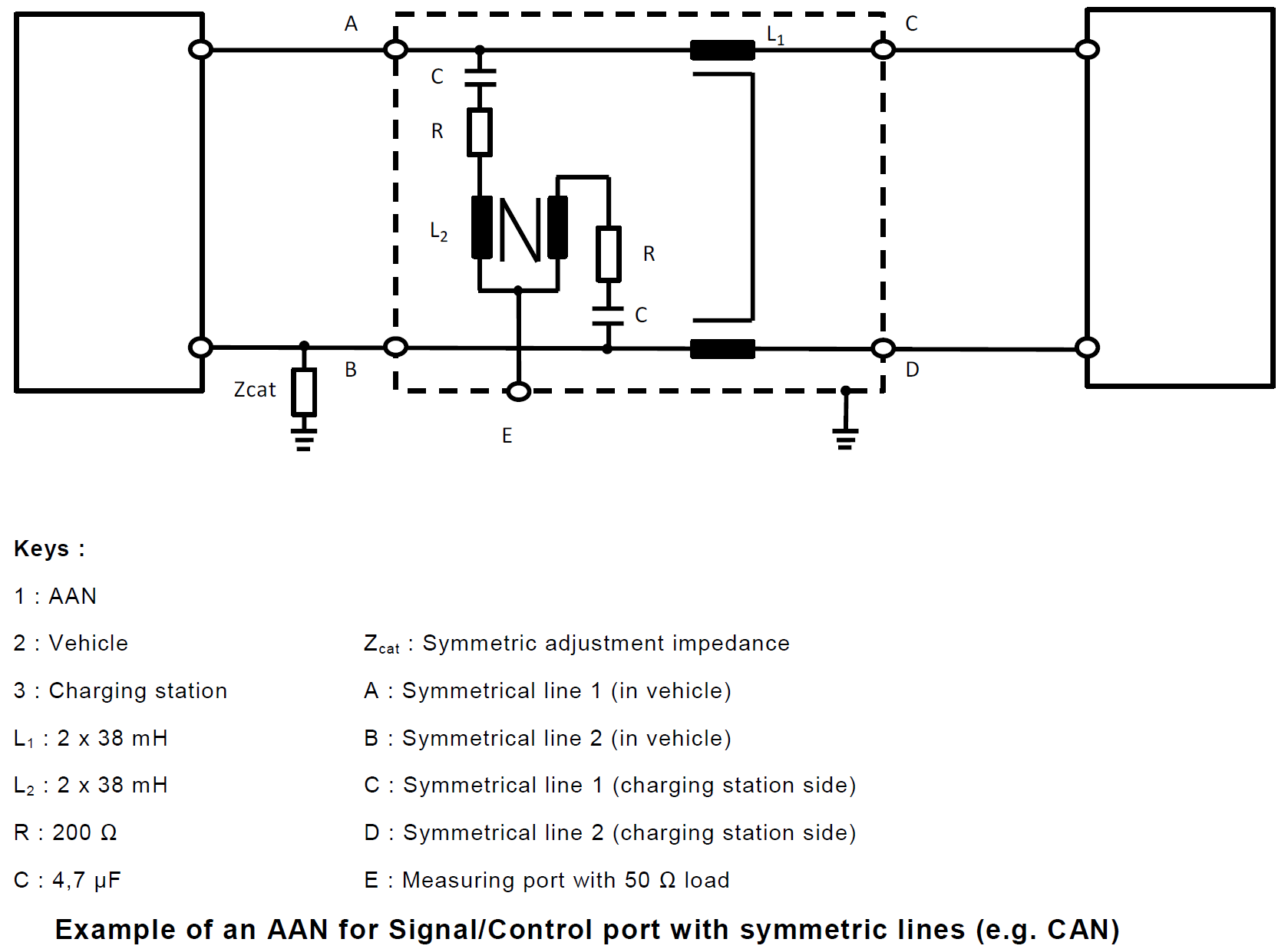
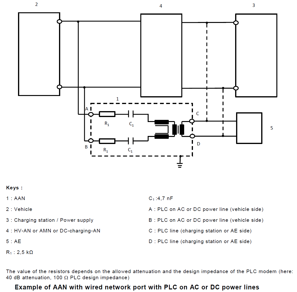
5. Asymmetric Artificial Network (AAN): used for signal/control port lines and/or wired network port lines.
1. Artificial Network (AN)
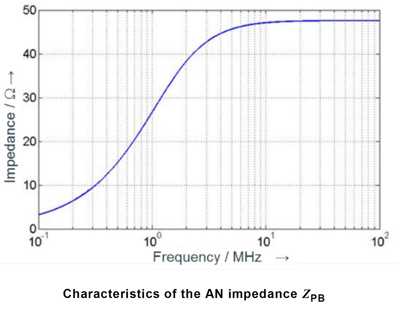
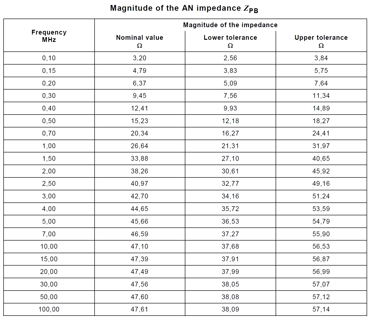
Measurement ports of HV-AN(s) must be terminated with a 50 Ω load. The HV-AN impedance ZPB (tolerance ± 20 %) in the measurement frequency range of 0.1 MHz to 100 MHz. This table above shows the nominal impedance and upper/lower tolerances in tabular form. It is measured between the EUT HV and ground terminals with a 50 Ω load on the measurement port and with the supply line HV and ground terminals short circuited.
2. High Voltage Artificial Network (HV-AN)
3. Direct Current charging Artificial Network (DC-charging-AN)
4. Artificial Mains Network (AMN)
Power mains must be applied to the vehicle through 50 μH/50 Ω AMN(s). The DC resistance between the ground of the AMN measurement port and the ground plane must not exceed 2,5 mΩ.
5. Asymmetric Artificial Network (AAN)
Christian Rosu
2021-06-22
In EMC "dropout" means Battery drops to 0V. FMC1278R3 (CI 260) is an example of various combinations of such battery voltage dropouts. The problem is that no automotive battery can really drop its output to 0V for say 5 seconds as well as for 50 ms without to blowout a fuse.
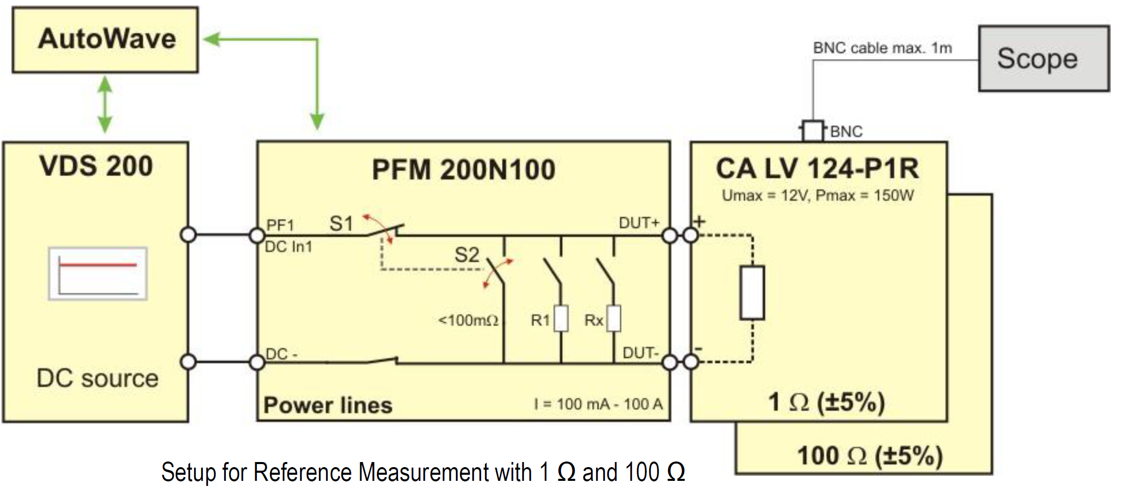
Therefore the only way to simulate correctly a “battery drop to 0V” is to disconnect DUT's B+ line from battery. The test equipment offers such capability to momentarily disconnect the battery during “voltage dropout” simulating a “0V” like condition, practically no current through supply lines to DUT.
This involves the use of PFM200N + VDS200Q + AutoWave to generate the CI 260 type of pulses. PFM200N acts like a very fast switcher disconnecting its output from DUT. So far only FCA (CS.00054) figure it out to ask “open condition” during “0V” battery voltage dropouts.
In EMC we use the wording “voltage dip” to describe a momentary battery voltage drop (e.g. 4.5V) below minimum supply voltage (e.g. 9V). Obviously in this scenario the Battery B+ line is not disconnected from DUT during the “voltage dip to 4.5V” of 100ms.
Christian Rosu Feb 17, 2021
Antenna factor when properly applied to a field strength meter reading yields:
- electric field intensity (V/m)
- magnetic field intensity (A/m).
The field intensity in the far-field radiation pattern of an antenna:
- Is proportional to the square root of the effective radiated power. Increasing the effective radiated power four times , the field intensity will be doubled.
- Is direct proportional to antenna current. If the far-field intensity in the far-field antenna pattern is doubled the antenna current will increase 2 times.
For a radio (transmitter or receiver) to deliver power to an antenna, the impedance of the radio and transmission line must be well matched to the antenna's impedance.
The parameter VSWR is a measure that numerically describes how well the antenna impedance is matched to the radio or transmission line it is connected to.
The voltage component of a standing wave in a uniform transmission line consists of the
- forward wave (with complex amplitude
 ) superimposed on the
 - reflected wave (with complex amplitude
 ).
).
A wave is partly reflected when a transmission line is terminated with other than an impedance equal to its characteristic impedance.
The reflection coefficient  can be defined as:
= Vr / Vf
is a complex number that describes both the magnitude and the phase shift of the reflection. The simplest cases with measured at the load are:
-
 complete negative reflection, when the line is short-circuited,
 -
 no reflection, when the line is perfectly matched,
 -
 complete positive reflection, when the line is open-circuited.
The voltage standing wave ratio is then:
See Tutorials