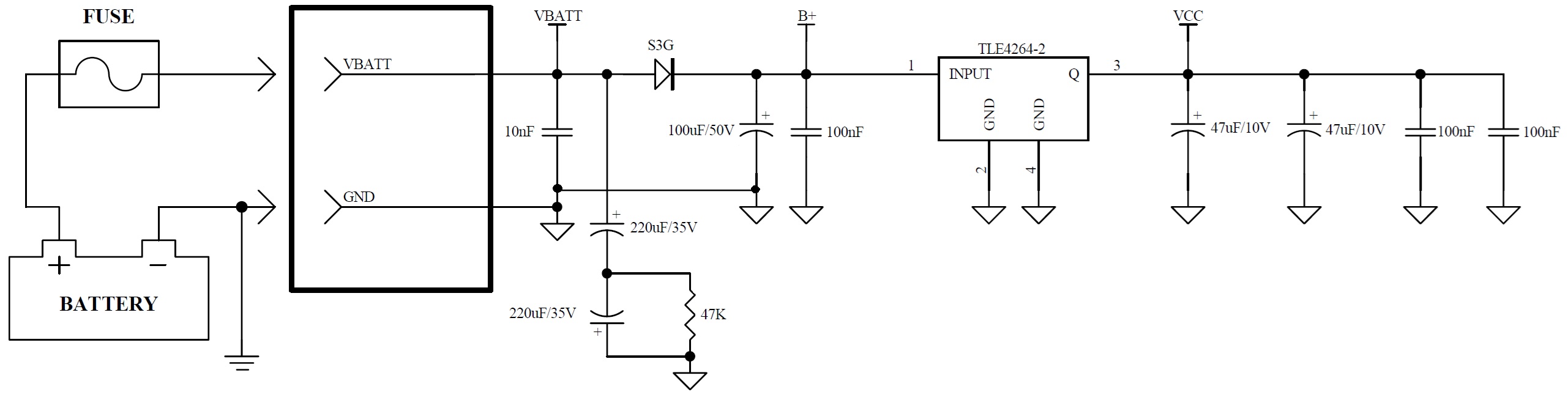
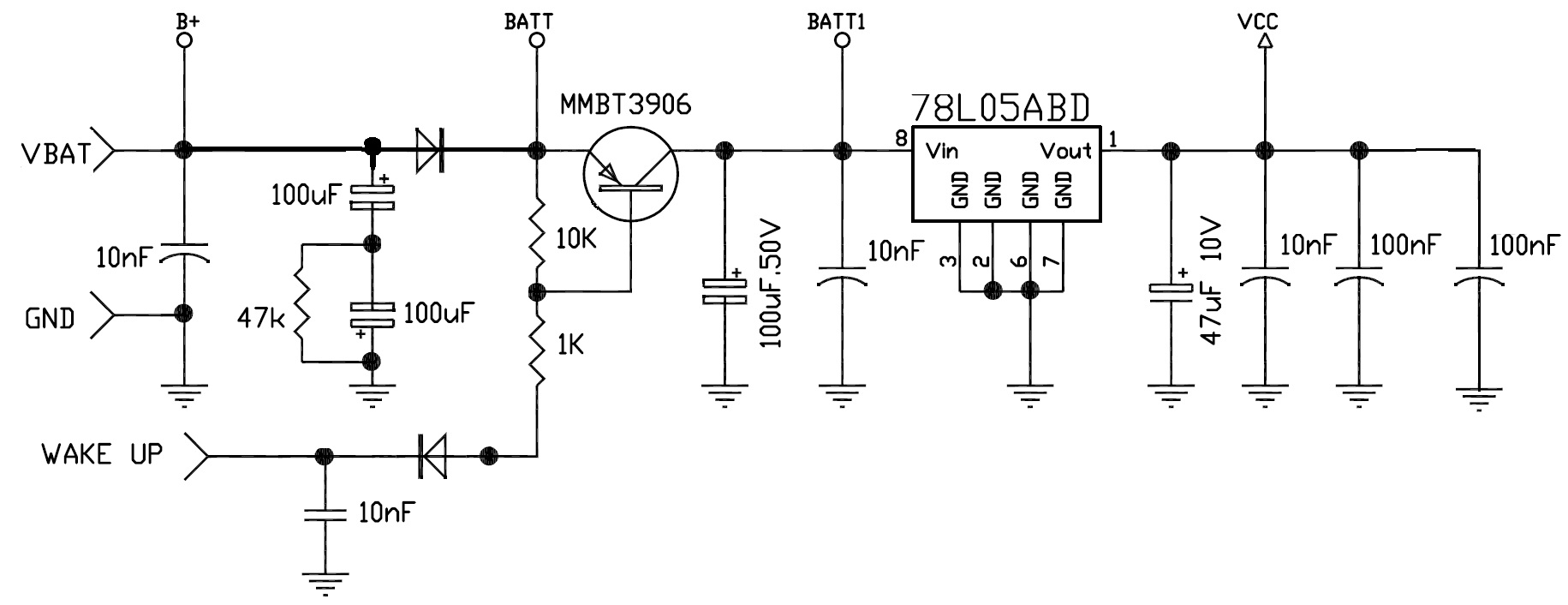
A standard 12V supply line input must withstand ISO 7637-2 supply line transients, ISO 16750-2 electrical testing, and specific OEM electrtical testing.
Christian Rosu
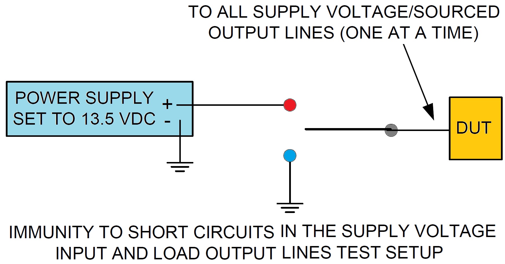
1. Immunity to Short Circuits in the Supply Voltage Input and Load Output Lines
- Using 13.5 Volts on all supply lines, verify proper DUT operation.
- Connect a power supply to one supply line or load output line, set it for 13.5 volts. Then, switch it from the 13.5 volts to ground for 5 seconds.
- Repeat the above process for all supply lines and load output lines verifying proper operation each time.
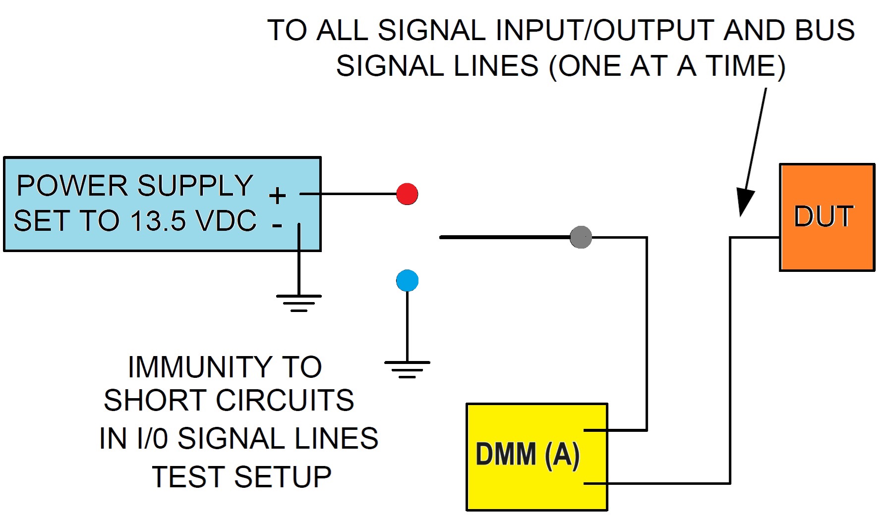
2. Immunity to Short Circuits in I/O Signal Lines
- Using 13.5 Volts on all supply lines, verify proper DUT operation.
- Connect a power supply to one I/O line, set it for 13.5 volts.
- Record the steady state current. Then, switch from the 13.5 volts to ground.
- Repeat the above process for all I/O lines verifying proper operation each time.
- Unless the test plan specifies otherwise, maximum steady state current recorded shall be less than 200 mA.
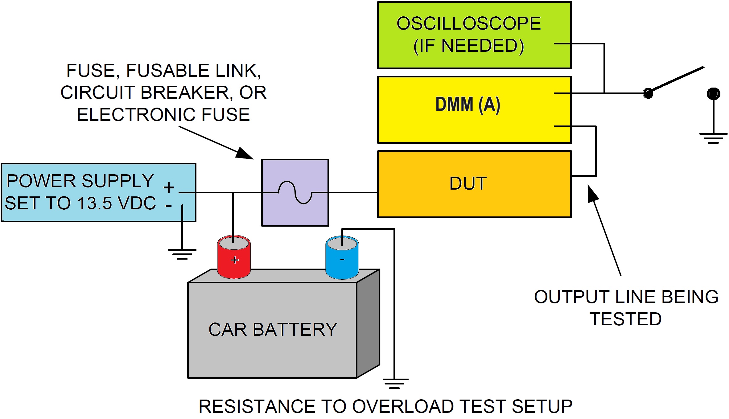
3. Resistance to Overload
- Fuses/Fusible Links/Circuit Breakers - short the output line to ground using the switch and measure both the current and time needed to open the circuit protection device. The current and time values and limits shall be given in the test plan. If no circuit protection device is used the DUT shall withstand a short circuit to ground for five minutes without damage to the DUT.
- Electronic Breakers - short the output line to ground using the switch and measure both the current and the time needed to open the circuit protection device. Verify proper operation of the Electronic Breaker and DUT per test plan.
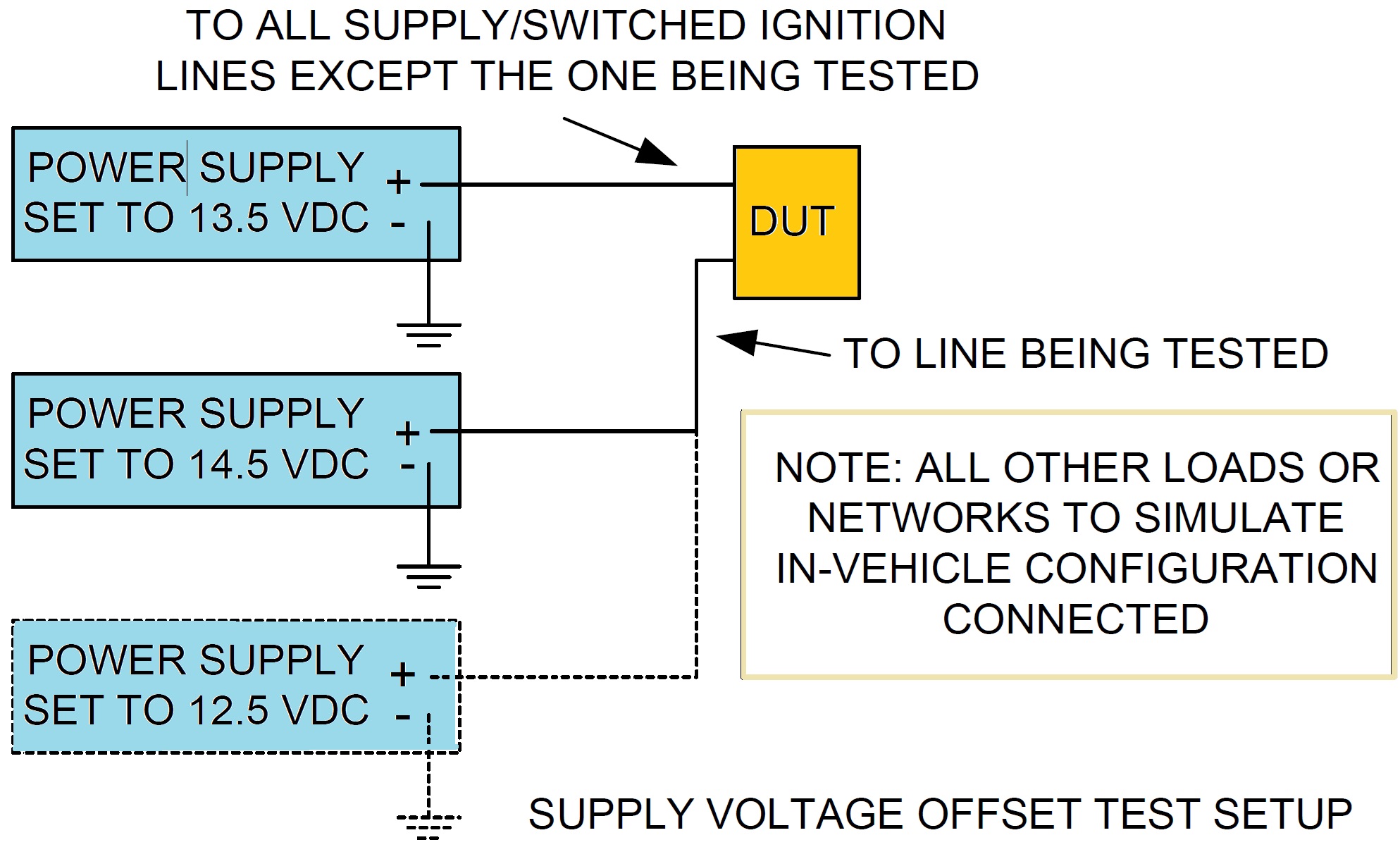
4. Supply Voltage Offset
- Using 13.5 Volts on all supply lines, verify proper DUT operation.
- Connect a power supply to one supply line, set it for 14.5 volts, and verify proper DUT operation. Repeat for 12.5 volts.
- Repeat the above two steps for all battery and switched ignition supply lines in any combination.
- Repeat entire procedure two more times for a total of three complete measurement cycles.
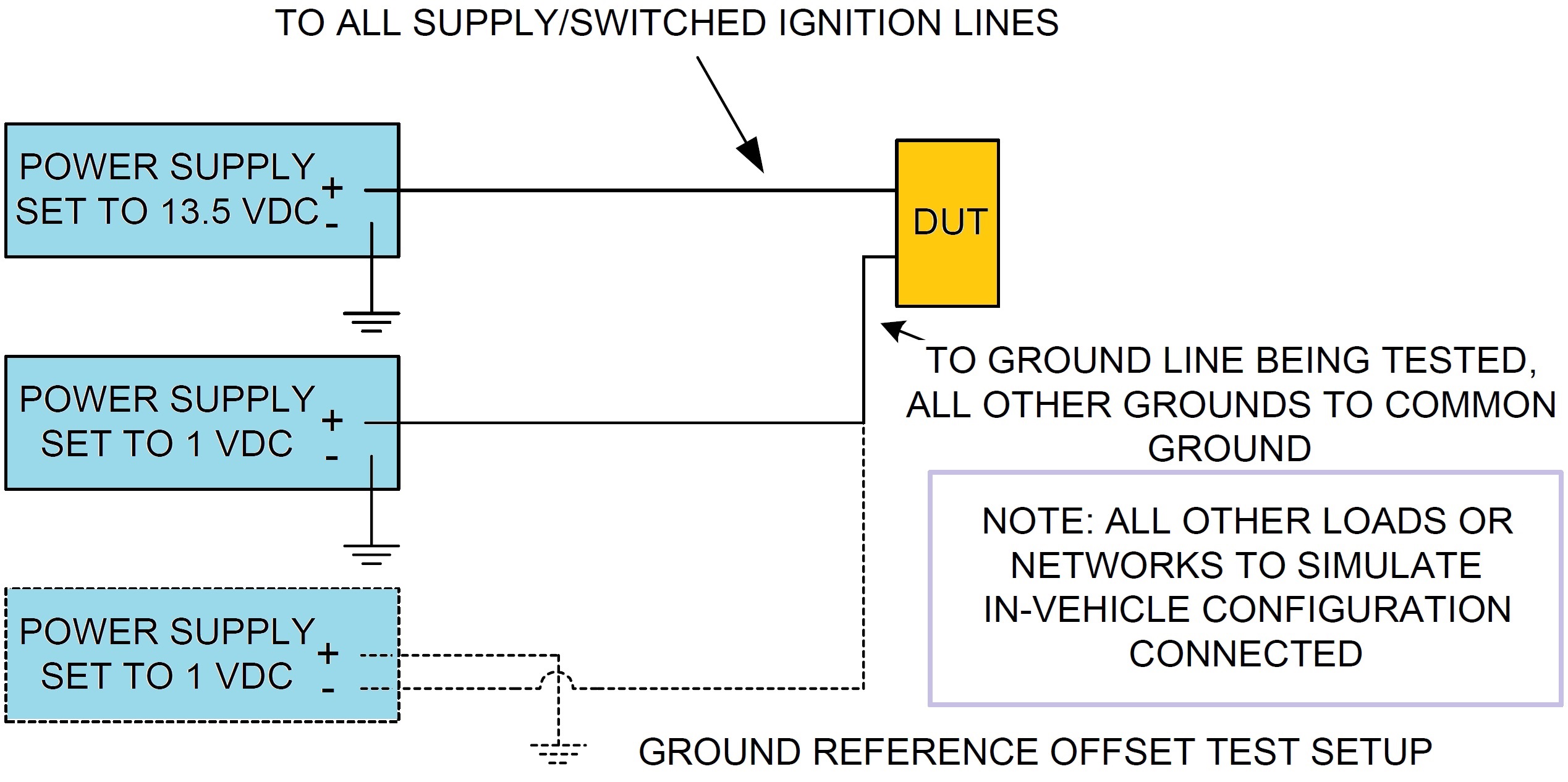
5. Ground Reference Offset
- Apply a 13.5 Volt supply voltage to the DUT and verify proper operation.
- Connect a power supply to one ground line, set it for 1 volt, and verify proper DUT operation.
- Repeat for –1 volt.
- Repeat the above two steps for all ground paths in any combination.
- Repeat entire procedure two more times for a total of three complete measurement cycles.
Christian Rosu
This test is intended to measure the level of harmonics generated by the DUT in configuration "REESS charging mode coupled to the power grid" through its AC power lines in order to ensure it is compatible with residential, commercial and light industrial environments.
REESS means the rechargeable energy storage system that provides electric energy for electric propulsion of the vehicle
This CE testing must be performed per:
1. IEC 61000-3-2 for input current in charging mode ≤ 16 A per phase;
2. IEC 61000-3-12 for input current in charging mode > 16 A and ≤ 75 A per phase.
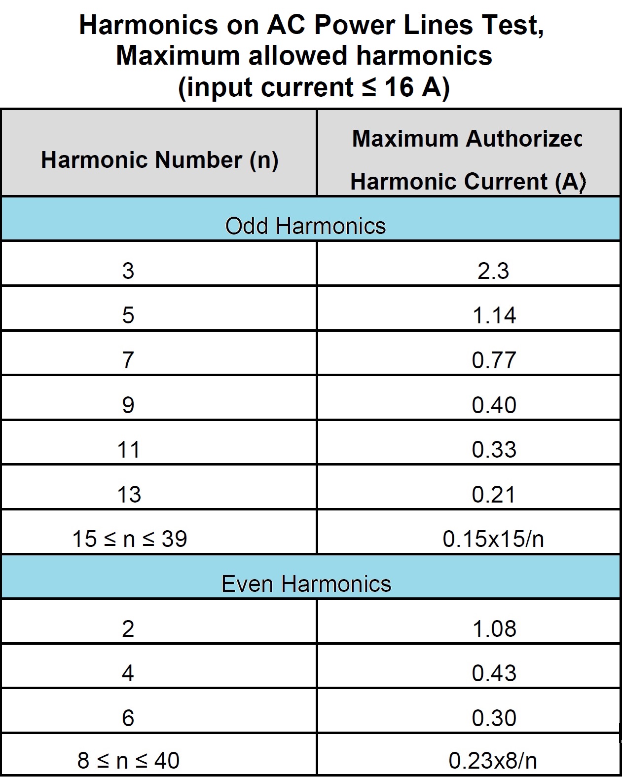
The measurements of even and odd current harmonics shall be performed up to the 40th harmonic.
The limits for single phase or three-phase DUTs in configuration "REESS charging mode coupled to the power grid" with input current ≤ 16 A per phase are given in Table 1 below:
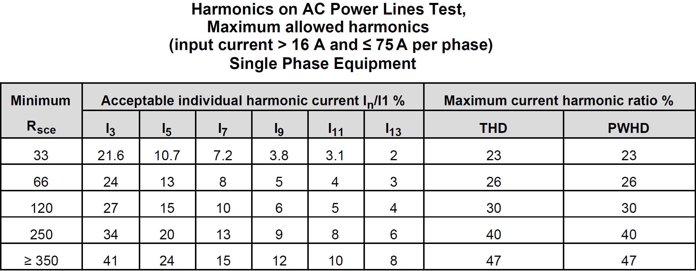
The limits for single phase DUTs in configuration "REESS charging mode coupled to the power grid" with input current > 16 A and ≤ 75 A per phase are given in Table 2 below:
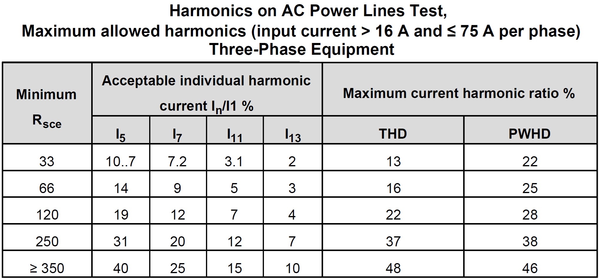
The limits for three-phase DUTs in configuration "REESS charging mode coupled to the power grid" with input current > 16 A and ≤ 75 A per phase are given in Table 3 below:
Test Setup and Procedure
- The DUT must be in configuration "REESS charging mode coupled to the power grid".
- The state of charge (SOC) of the traction battery shall be kept between 20 per cent and 80 per cent of the maximum SOC during the whole time duration of the measurement (this may lead to the measurement being split into different time slots with the need to discharge the vehicle’s traction battery before starting the next time slot).
- If the current consumption can be adjusted, then the current shall be set to at least 80 per cent of its nominal value.
- The observation time to be used for the measurements shall be as for quasi-stationary equipment as defined in Table 4 of IEC 61000-3-2.
- The test set-up for single phase DUT in configuration "REESS charging mode coupled to the power grid" is shown in Figure 1 of Appendix 1 to Annex 17, ECE Regulation 10.
- The test set-up for three-phase DUT in configuration "REESS charging mode coupled to the power grid" is shown in Figure 2 of Appendix 1 to Annex 17, ECE Regulation 10.
CISPR 25:2021 6.4.3 Test procedure ... The current probe shall be mounted around the complete harness (including all wires). If the EUT has multiple connectors on the unit resulting in multiple wire bundles, the test plan shall define which wires shall be included in the probe for measurement. In the absence of any definition, measurements shall be made for each bundle (connector) separately as well as combined (i.e. all together).
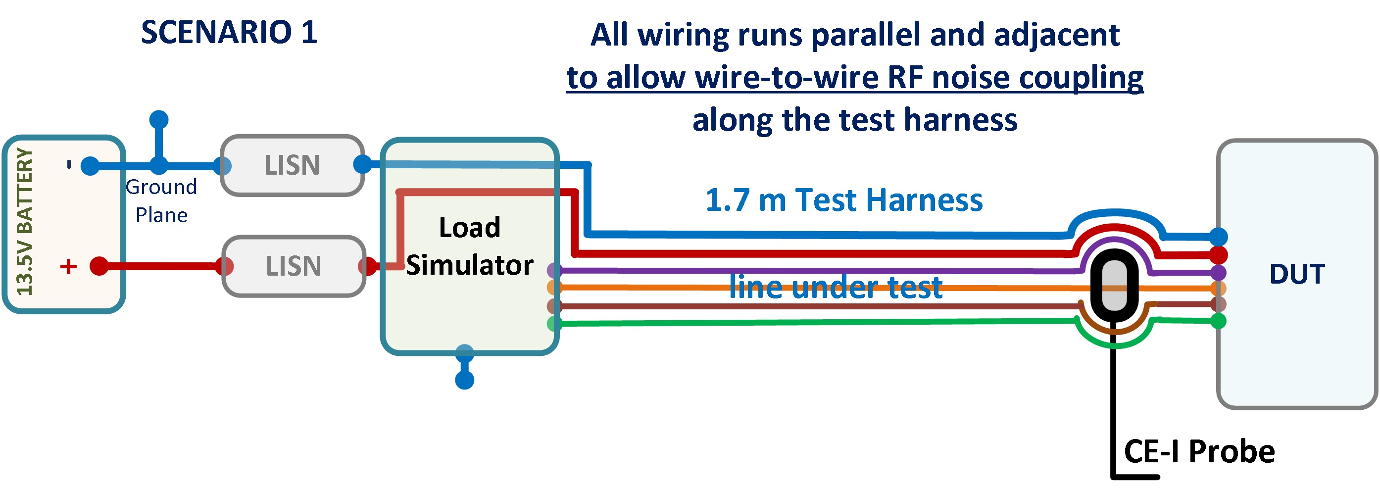
CISPR 25:2021 6.4.2.2 Location of the test harness: …. The test harness wires shall be nominally parallel and adjacent unless otherwise defined in the test plan.
We normally want to capture noise from wire-to-wire coupling, that’s why all wiring must run parallel and adjacent along the test harness except for the portion of wire/connector with CE-I probe clamped on it. Scenario #1 below shows the correct test harness and wiring layout.
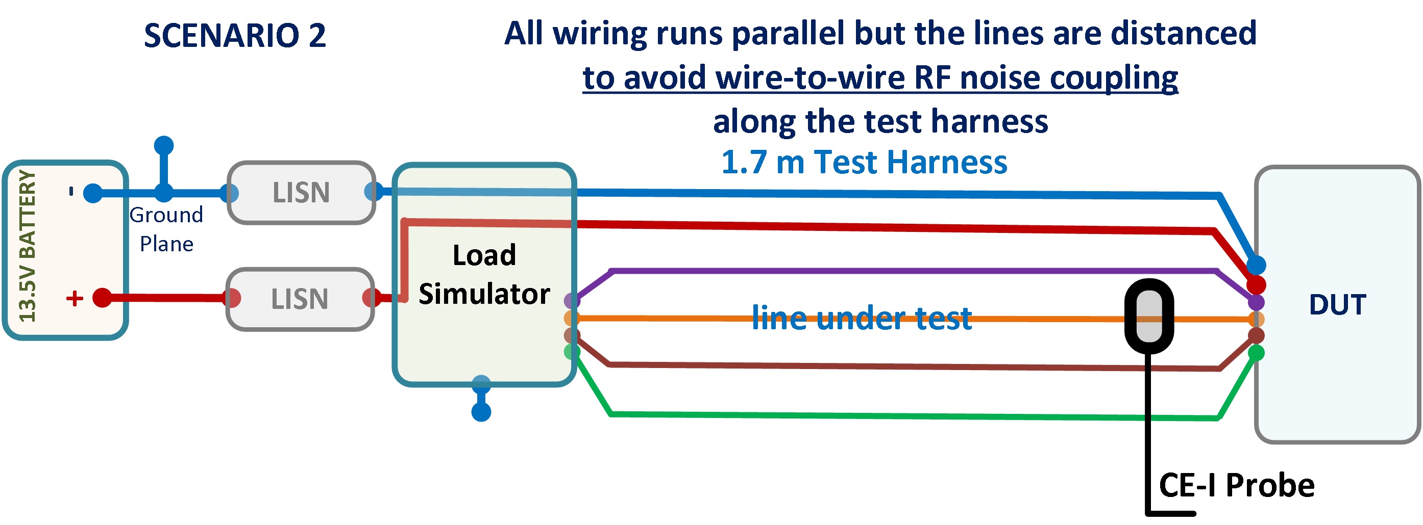
Scenario #2 is incorrect since CISPR 25 require "parallel and adjacent" wiring. CISPR 25 does not define a minimum or maximum distance between the wires included in the test harness.
Christian Rosu