EMC FLEX BLOG A site dedicated to Automotive EMC Testing for Electronic Modules

Calibrating Filed Probes for Automotive EMC Standards

24. February 2020 09:31 by Christian in EMC/EMI, Test Methods, Calibrations, Uncertainty
IEEE 1309:2013 is the Standard for Calibration of Electromagnetic Field Sensors and Probes (Excludin

The accuracy of RF Field Level during ALSE RF Immunity per ISO 11452-2:2019 Substitution Method relies on the Field Probe calibration factors. An incorrect Field Probe Calibration may result in significant deviations from the field levels called by automotive OEM specs. The Field Probe Calibration Report provides correction factors that are introduced into RF Immunity Test Software (e.g. TILE, NEXIO). Using calibration factors acquired at 15 V/m instead of 300 V/m can force the RF Amplifier output to maximum w/o the Field Probe to report expected Field Level. Moving transmitting antenna 10 inches closer to the Field Probe would allow the probe to report the expected field level, however this level is in fact higher as consequence of using bad correction factors.

RF Field Probe Selection for EMC Testing

Calibration Factors: corrections are provided as dB adjustments & multiplication factors. Maximum field measurement accuracy is achieved when the detailed 3-axis calibration is applied.

     Probe Calibration Certificate

     A) filed level applied via calibration antenna (V/m)

     B) filed level reported by probe (V/m)

     C) calculated multiplier factor

          A = B * C (e.g. 100 V/m = 120 V/m x 0.8333 where 0.8333 is the correction factor)

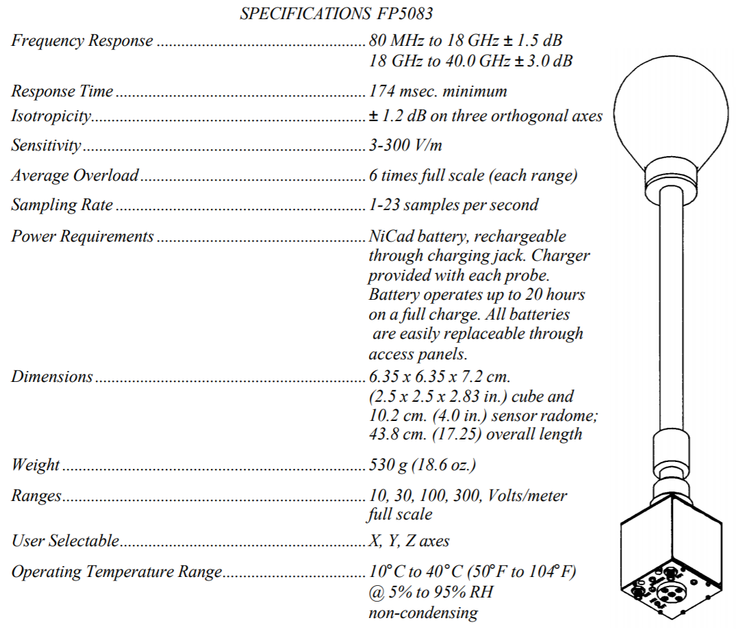
Sensitivity/Dynamic Range: e.g. (0.5 – 800V/m for 0.5 MHz – 6 GHz)

Linearity: the measure of deviation from an ideal response over the dynamic range of the probe that may vary as a function of the applied field level. (e.g. ±0.5dB 0.5 – 800 V/m).

Overload: the field level where damage can occur to the probe (e.g. 1000 V/m CW).

Isotropic Deviation: the variation of the probe’s response from ideal as it is rotated in the field. The minimal isotropic deviation of spherical probes (±0.5dB 0.5 MHz – 2 GHz).

Response time: the time a probe takes to respond to an applied RF field (e.g. 20 ms).

Sample rate: the rate at which information can be retrieved from the probe (e.g. 50 samples/second). 

Probe Type: refers to the configuration of the probe sensors. 


  • An isotropic RF filed measures the total value of the field level and is unaffected by field polarity. This is accomplished by summing measurements from three different sensors placed orthogonal to each other. 
  • Non-isotropic probes measure fields in one polarity at a time for electric field or magnetic field. 


IEEE 1309:2013 is the Standard for Calibration of Electromagnetic Field Sensors and Probes (Excluding Antennas) from 9 kHz to 40 GHz. 

The EMC lab must inform the calibrator about critical requirements imposed by automotive specs/standards for proper field calibration factors:


  1. The frequency range or center frequencies as delineated by automotive OEM EMC specs (e.g CS.00054, GMW3097, FMC1278).
  2. The filed level for each frequency band (e.g. 80V/m, 100V/m, 200V/m, 300V/m)
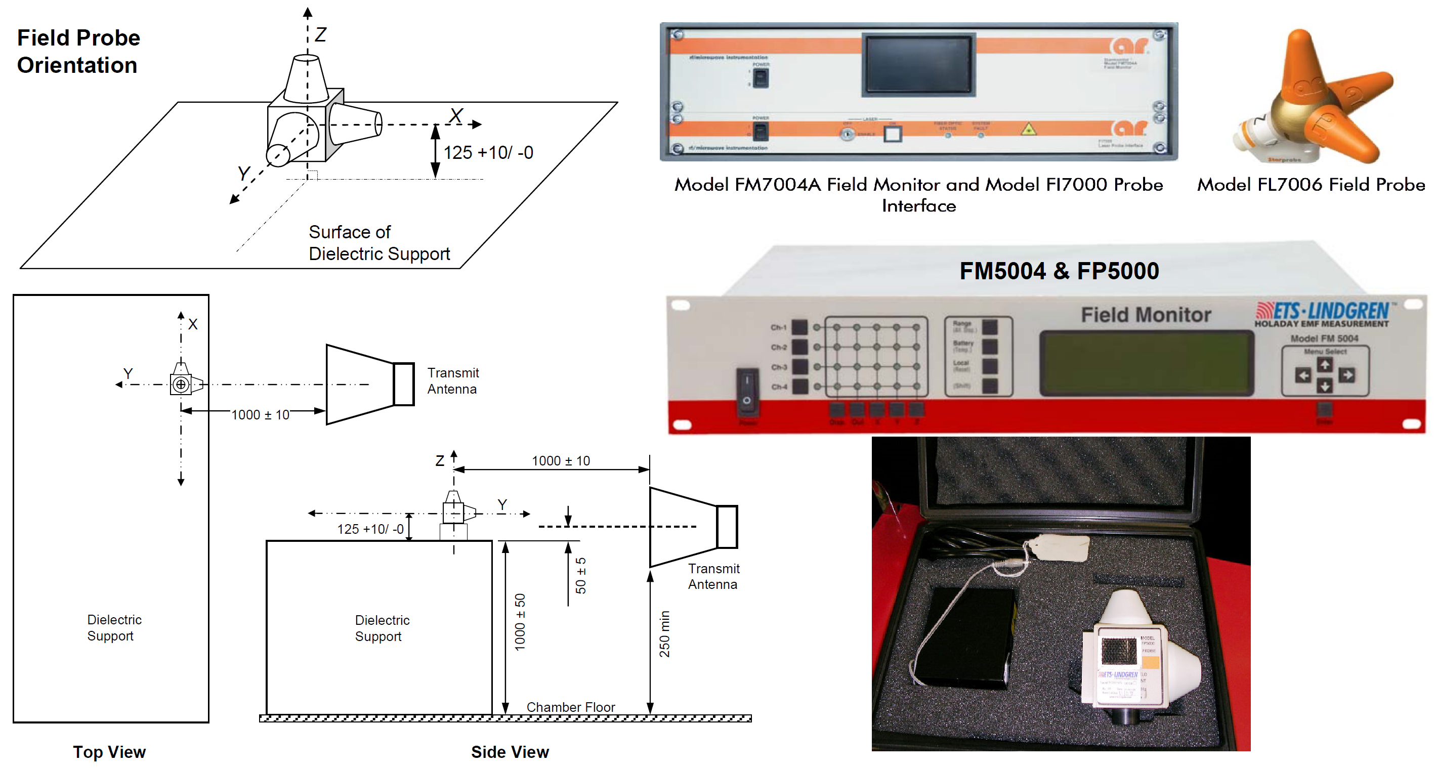
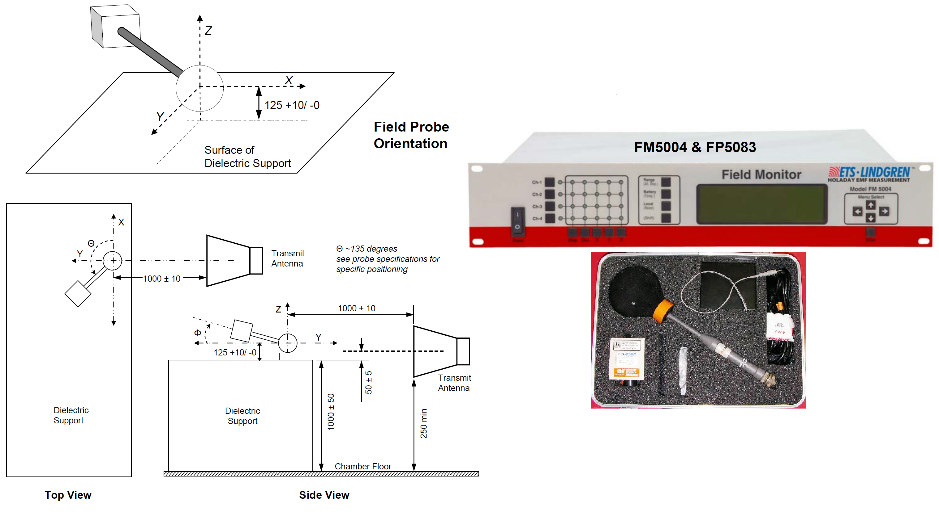
  3. Field Probe orientation (all three axes X, Y, Z facing antenna).
  4. Use 1 meter antenna distance to Field Probe. This is not always possible, therefore using a lower distance in far field  (e.g. 30 cm) should be acceptable.
  5. Calibrate the probe using CW with transmitting antenna in both horizontal/vertical polarization.


IEEE 1309:2013 A.2.4.3 Field strength: if the probe or sensor linearity is better than ± 0.5 dB, the frequency response calibration of the probe can be performed at any field strength level, but preferably close to the field levels used in the EUT tests. It is also required that the same probe range and/or gain settings as used in the EUT tests are used in the probe calibrations.

IEEE 1309:2013 A.2.4.4 Linearity check for probe or sensor:

For applications needing multiple field strength calibrations, e.g., 3 V/m, 10 V/m, and 18 V/m, the linearity tests shall be performed for each level. Note that for automotive EMC testing the above e.g. translates to levels like 100V/m, 200V/m, 300V/m.

IEEE 1309:2013 A.2.4.5 Probe isotropic response

For isotropic probes using three orthogonal elements, it is recommended that the frequency response and linearity response measurements be performed for each axis individually. Each axis should be aligned with the incident field successively to provide a maximum response. Probe calibration in a single orientation, such as only the orientation used in a UFA calibration, is not recommended, because the transmitting antennas, separation distances, and the end-use environment are typically not the same between the two setups.

Example of RI ALSE Test Configuration
 
 
Example of Field Calibration using Field Probe Type A per FMC1278R3 

 
Example of Field Calibration using Field Probe Type B per FMC1278R3 


Example of Field Probe Specs (AR FP5082)


References: IEEE 1309:2013, ISO 11452-2, FMC1278 Rev3, 28401NDS02 [8], AR App Note #44
Christian Rosu, Feb 24, 2020
 

AR_App_Note_44_RF_Field_Probe_Selection.pdf (352.8KB)

Rhode & Schwarz Equipment Calibration Interval:

https://gloris.rohde-schwarz.com/anonymous/en/pages/toplevel/calibration-process.html

Compliance to CISPR-25 Conducted Emissions Voltage

8. February 2020 07:30 by Christian in
When comes to achieving EMC compliance for automotive specs a 2-layer PCB works only for very simple

When comes to achieving EMC compliance for automotive specs a 2-layer PCB works only for very simple designs. Modules having CAN/LIN, USB, E-Net, LVDS are normally using 4-layer PCBs. If adding CPU and memory a 4-layer PCB may not be good enough.

Ford (FMC) mentioned 20 years ago in their EMC design guide for 2-layer PCB to use the “Ground Grid Technique” for top and bottom side of PCB. They also recommended the use of "Faraday Cage" by installing ground vias around the perimeter of the PCB every say 15mm that are connected together on both PCB sides by 0.4 mm thick traces.

The problem with CE-V is that even using a “ground grid” or “faraday cage” won’t prevent DUT’s noise to be coupled into Supply Lines. Assuming that in your case CE-V are higher on GND line I would:

  1. determine potential sources of noise with harmonics in FM band
  2. determine the noise coupling method (e.g. common mode current, common return path, ground loops)
  3. Clamp ferrite corres on the entire test harness to lower CE-V noise below limit. Clamp the same ferrite separately on VBATT or GND line to determine which one is more affected. 

RF filters are effective for emissions exceeding the limit with 2-3 dB. For conducted emissions exceeding the limit with 10 dB you better try to fix the layout first.


Christian Rosu Feb 8, 2020.

CAN Bus Hardware Verification

4. February 2020 04:46 by Christian in
CAN Bus TerminationThe termination is used to match impedance of a node to the impedance of the tran

CAN Bus Termination

The termination is used to match impedance of a node to the impedance of the transmission line being used. When impedance is mismatched, the transmitted signal is not completely absorbed by the load and a portion is reflected back into the  transmission line. If the source, transmission line and load impedance are equal these reflections are eliminated. This test measures the series resistance of the CAN data pair conductors and the attached terminating resistors.

1. Turn off all power supplies of the attached CAN nodes.

2. Measure the DC resistance between CAN_H and CAN_L at the middle and ends of the network.

The measured value should be between 50 and 70 Ω. The measured value should be nearly the same at each point of the network. If the value is below 50 Ω, please make sure that:

- there is no short circuit between CAN_H and CAN_L wiring

- there are not more than two terminating resistors

- the nodes do not have faulty transceivers.

If the value is higher than 70 Ω, please make sure that:

- there are no open circuits in CAN_H or CAN_L wiring

- your bus system has two terminating resistors (one at each end) and that they are 120 Ω each.


CAN_H/CAN_L Voltage Verification

Each node contains a CAN transceiver that outputs differential signals. When the network communication is idle the CAN_H and CAN_L voltages are approximately 2.5 volts. Faulty transceivers can cause the idle voltages to vary and disrupt network communication. To test for faulty transceivers, please

1. Turn on all supplies.

2. Stop all network communication.

3. Measure the DC voltage between CAN_H and GND

4. Measure the DC voltage between CAN_L and GND

Normally the voltage should be between 2.0 V and 4.0 V. If it is lower than 2.0 V or higher than 4.0 V, it is possible that one or more nodes have faulty transceivers. For a voltage lower than 2.0 V please check CAN_H and CAN_L conductors for continuity. For a voltage higher than 4.0 V, please check for excessive voltage.


CAN Bus Ground Verification

The shield of the CAN network has to be grounded at only one location. This test will indicate if the shielding is grounded in several places: 

1. Disconnect the shield wire (Shield) from the ground.

2. Measure the DC resistance between Shield and ground.

3. Connect Shield wire to ground.

 The resistance should be higher than 1 M Ω. If it is lower, please search for additional grounding of the shield wires.


CAN Transceiver Resistance Test

CAN transceivers have one circuit that controls CAN_H and another circuit that controls CAN_L. Experience has shown that electrical damage to one or both of the circuits may increase the leakage current in these circuits. To measure the current leakage through the CAN circuits, please use an resistance measuring device and:

1. Disconnect the node from the network. Leave the node unpowered.

2. Measure the DC resistance between CAN_H and CAN_GND.

3. Measure the DC resistance between CAN_L and CAN_GND.

Normally the resistance should be between 1 M Ω and 4 M Ω or higher. If it is lower than this range, the CAN transceiver is probably faulty.