30. July 2015 07:39 by streng in
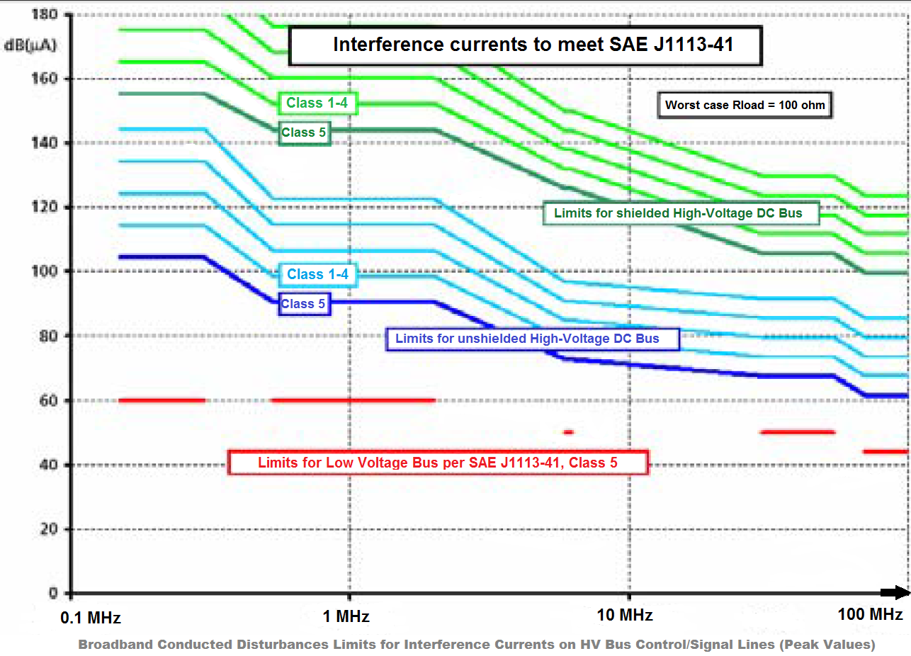
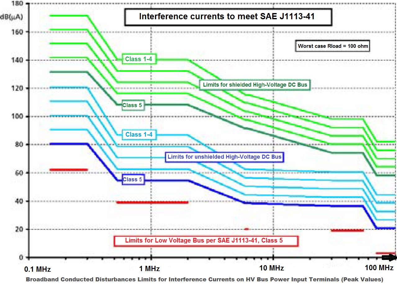
EV require higher power for the electric drive components and higher voltage (900 V) in the high voltage bus. The HV Bus is built as a completely insulated power supply network with cables most often shielded.
The main components of the automotive electric drive are:
- electric motor (the connection between converter and motor must be very short)
- power converter (the main source of EMI due to high speed switching devices with changing pulse patterns)
- power supply (traction battery providing power to the converter is a main part of the path for EMI)
- lines connecting the above components
Each of these components acts as a path for electromagnetic emissions:
- RF noise emissions due to the ratio between the size of the power converter and the frequency of the EMI.
- The high-voltage system is insulated and does not use the car body as return conductor like the low-voltage supply system. However, the high-voltage and the low voltage cables are arranged closely to each other, one important coupling path being the crosstalk between the different lines.
- The drive system can be either noise source or part of the coupling path within EV electrical system.
21. July 2015 22:39 by Christian in
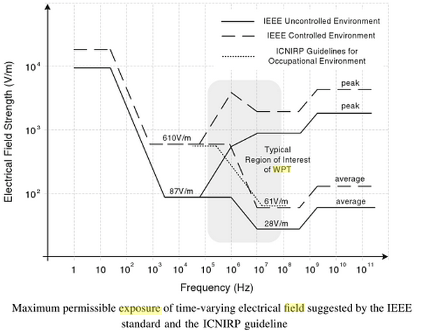
Human Model at the worst radiation point during slow EV charging.
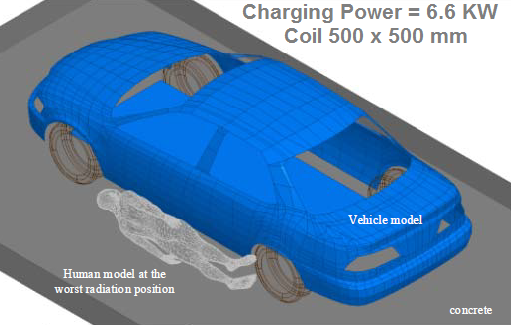
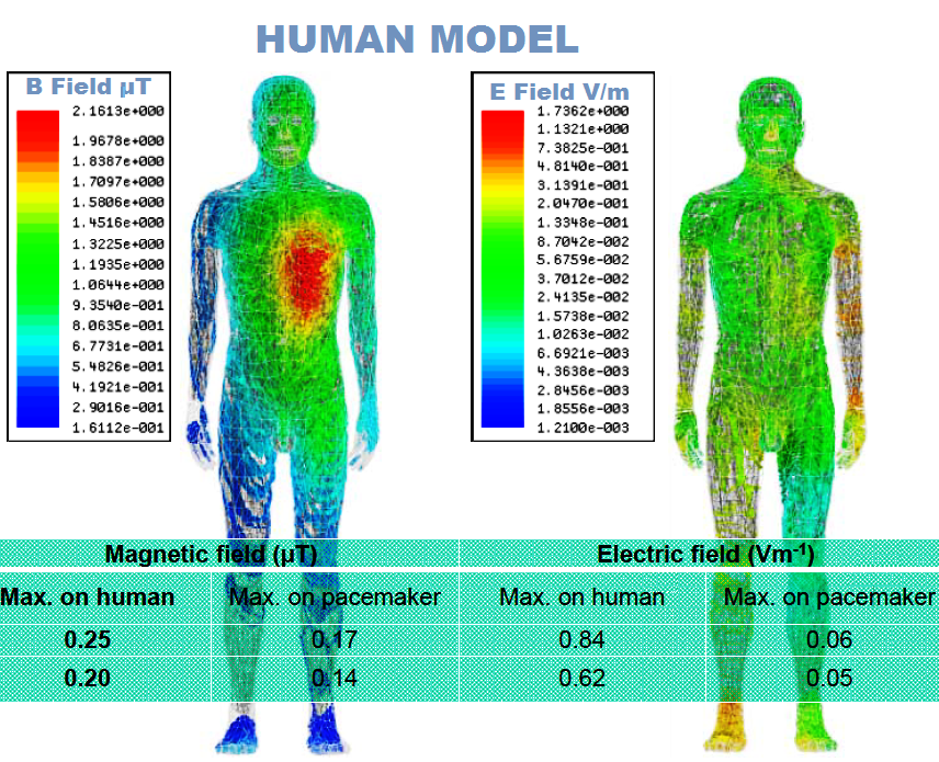
Sources: University of Michigan-Dearborn
21. July 2015 22:01 by Christian in
EV Charging Time & Power Requirement |
Range | 5
minutes | 15
minutes | 30
minutes | 8
hours |
100 miles | 390 kW | 130kW | 65kW | 4 kW |
400 miles | 1560 kW | 520 kW | 260 kW | 16 kW |
Fast
charging shortcomings:
- it
may compromise battery life
- increased
cost for the charging stations
- power
grid heavy loading
20. July 2015 11:29 by Christian in
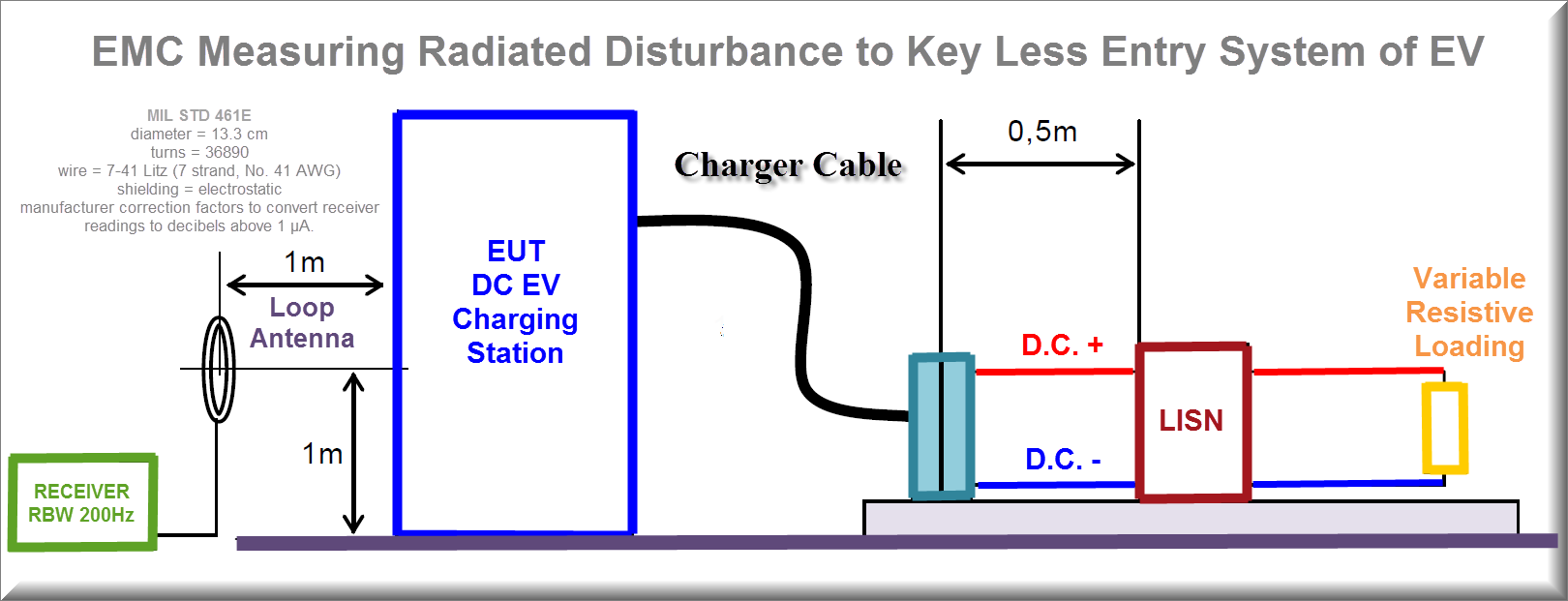
This test simulates the effects of the radiated magnetic fields on a keyless entry system due to close proximity to other vehicles charging systems. The charging equipment is connected to a resistive load that represents 100 % of the load of maximum.
1. Turn on the charging equipment and allow sufficient time for stabilization.
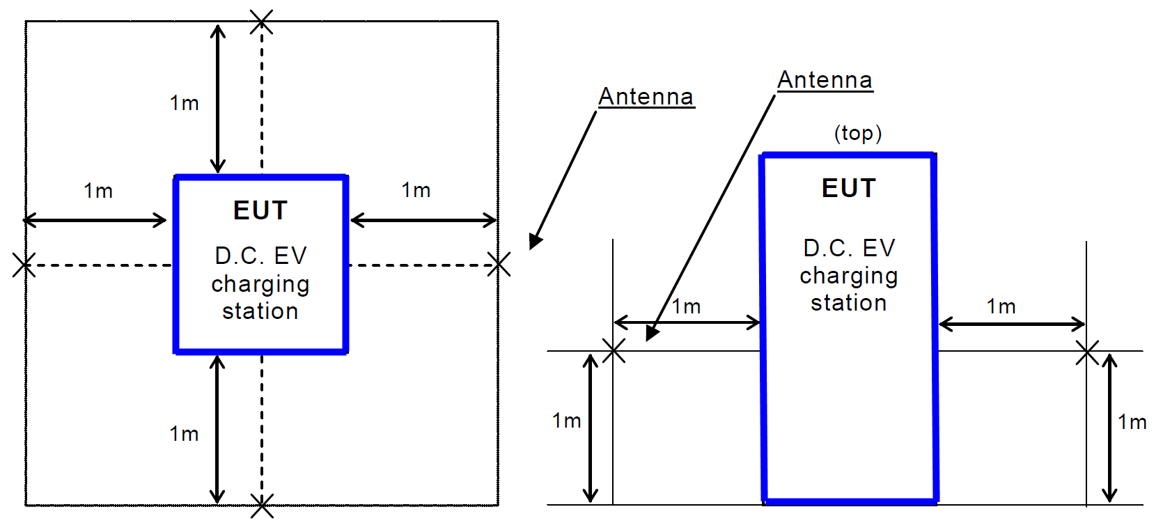
2. Locate the loop sensor 1 m from the charging equipment face or electrical interface connector being probed. Orient the plane of the loop sensor parallel to the charging equipment faces and parallel to the axis of connectors.
3. Scan the measurement receiver over the applicable frequency range to locate the frequencies of maximum radiation, using the bandwidths and minimum measurement times according to MIL STD 461 or CISPR 16-2-3.
4. Tune the measurement receiver to one of the frequencies or band of frequencies identified in step 3 above.
5. Monitor the output of the measurement receiver while moving the loop sensor (maintaining the 1 m spacing) over the face of the EUT or around the connector. Note the point of maximum radiation for each frequency identified in step 4.
6. At the point of maximum radiation, orient the loop sensor in the vertical plane to give a maximum reading on the measurement receiver and record the reading.
7. Repeat step 4 through step 6 for at least two frequencies of maximum radiation per octave of frequencies below 200 Hz and for at least three frequencies of maximum radiation per octave above 200 Hz.
8. Repeat step 2 through step 7 for each face of the EUT and for each EUT electrical connector.
Sources: MIL STD 461 or CISPR 16-2-3