27. April 2016 01:39 by Christian in
EMC/EMI The generic shielding effectiveness requirement is 40 dB for magnetic field, electric field, and plane waves. Depending on the application the frequency range can start from 10 Hz going up to GHz.
To predict shielding effectiveness (SE) of a metal sheet the following factors are summed: Absorption Loss (A), Reflection Loss (R), re-Reflection Correction Factor (C). SE = A + R – C (see MIL-HDBK-419A).
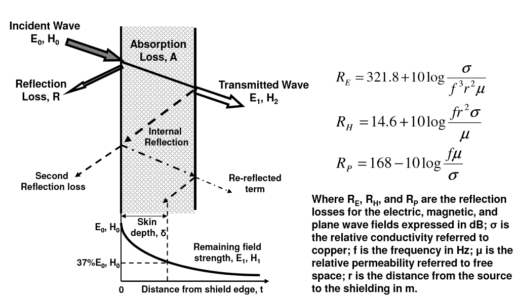
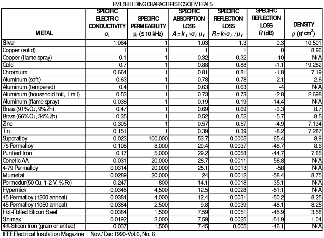
Absorption loss depends on material thickness, permeability, electrical conductivity, and the frequency of the incident wave. It is the same for all electromagnetic waves.
Reflection loss depends on the distance of the EMI source to the material (different for electric, magnetic, and plane waves), material electrical conductivity, and the frequency of the incident wave.
Sources:
Christian Rosu
3. April 2016 13:31 by Christian in
The Bulk Current Injection (BCI) test method simulates a field-to-wire coupling from nearby low frequencies radiated fields induced onto a test harness small relative to wavelength.
The coupling from BCI probe will increase with test frequency when the cable is electrically short, and then flatten out when the cable approaches and exceeds a half-wavelength in length.
The transducers (RF current transformers) inject current into both sides of the test harness, therefore both DUT and Load Simulator are subject to test. RF radiation from load simulator cables is possible, but it can be reduced placing 20cm of clip-on split-ferrite RF suppressers close to the transducer.
The BCI common-mode current injected in the test harness simulates an illuminating RF field.
To simulate conducted differential-mode disturbances the BCI induced current is injected in individul conductors.
Using the Substitution Method the actual current injected in test cables can vary from what was initially calibrated, being less likely to over-test but more real-life representative.
To ensure the repeatability of test results, the cable under test must be centered within BCI current probe, the test set-up must be consistent, especially cable routing, placement of the clamp, and proximity to metal structures.
BCI Calibration Levels per MIL STD 416F CS114:
BCI Probe Insertion Loss per MIL STD 416F CS114:
RF Immunity Ratio mA versus V/m per MIL STD 416F:
Ford RI 112 (BCI) Calibration Limits requirements per FMC1278: