12. June 2015 08:39 by streng in
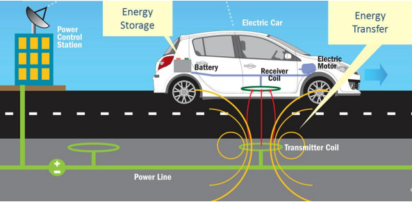
MF-WPT is the wireless transfer of energy from a power source to an electrical load via a magnetic field.
Magnetic coupling
The source of a magnetic flux is a coil structure. Power transfer will be initiated by positioning two or more coil structures near each other in a way that the time varying flux generated by the primary coil structure, passes through the windings of the secondary coil structure.
Primary and secondary coil structures for WPT systems interact through an air gap. Usually a centre plane in the air gap can be defined dividing the WPT system whereas the primary coil structure is completely located on one side of this plane and the complete coil structure of the secondary device is located on the other side of the plane. For a primary device and a secondary device to be interoperable, they shall be magnetically compatible.
MF-WPT Functions
- stand by and wake up: the supply device is woken up by the a signal from the EV.
- compatibility check: power classes, the operating frequency, magnetic coupling, circuit topology, tuning.
- initial alignment check: primary and secondary devices are properly well positioned relative to each other.
- start power transfer: transfer the power from the primary device to the secondary device upon the request from the vehicle
- time scheduled power transfer: no perform power transfer until the command and control communication is properly established and the primary device and secondary device are properly positioned.
- perform power transfer: MF-WPT system transfer the power from the primary device to the secondary device in accordance with the power demand of the EV. The maximum transferring power of the off-board MF-WPT system shall not be exceeded. The vehicle can change the requested transfer power.
- stop power transfer: MF-WPT system shall be able to stop transfer the power from the primary device to the secondary device in accordance with the demand of the EV. Th e vehicle can requested stop power transfer.
- user initiated stop power transfer: allow the user to terminate of power supply. e.g. pushing stop button.
- safety monitoring & diagnostics: command & control communication safety monitoring & diagnostics
- power transfer monitoring
- thermal monitoring
- live object protection
- failure conditions: short-circuit, earth leakage, excess temperature, insulation failure, overcurrent, overload
- continuous monitoring of power transfer conditions: the actual output power does not differ from the expected output power by a certain limit; if the limit is exceeded, it shall stop power transfer.
- continuous monitoring of command & control communication
- continuous monitoring of safety conditions
- Verify that the ventilation system of the area is functioning and active
10. June 2015 18:06 by streng in
CISPR11:2010 (Ed 5.1) applies to industrial, scientific and medical (ISM) electrical equipment operating in the frequency range 0 Hz to 400 GHz. Certain frequencies are designated by the International Telecommunication Union (ITU) for unrestricted radiation from ISM equipment.
AC Power Port - CISPR 11; Conducted disturbances (150kHz-30MHz)
Table 6 (Class A) - Mains terminal disturbance voltage limits for class A group 2 equipment measured on a test site
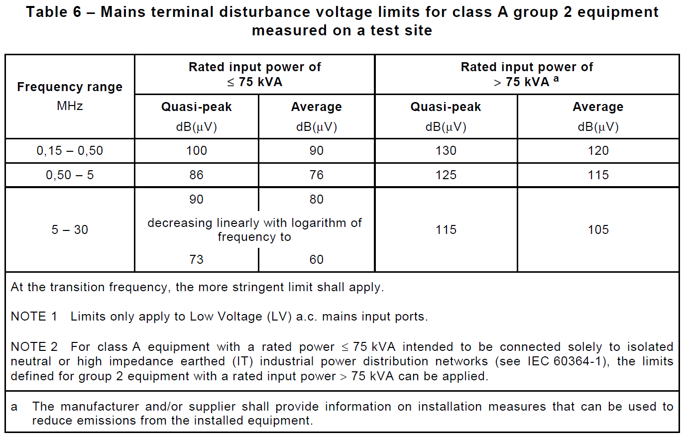
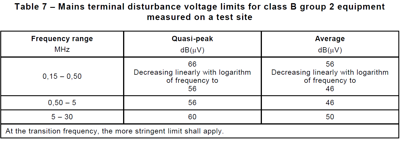
Table 7 (Class B) - Mains terminal disturbance voltage limits for class B group 2 equipment measured on a test site
WPT System and Enclosure Port - CISPR 11;
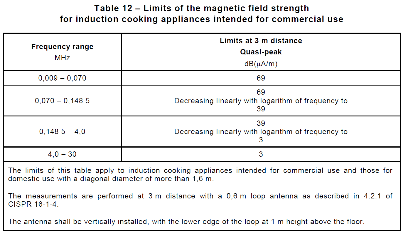
Table 12 - Limits of the magnetic field strength for induction cooking appliances intended for commercial use
WPT System Port - CISPR 11;
Table 6 (Class A) - Mains terminal disturbance voltage limits for class A group 2 equipment measured on a test site
Table 7 (Class B) - Mains terminal disturbance voltage limits for class B group 2 equipment measured on a test site
8. June 2015 18:47 by streng in
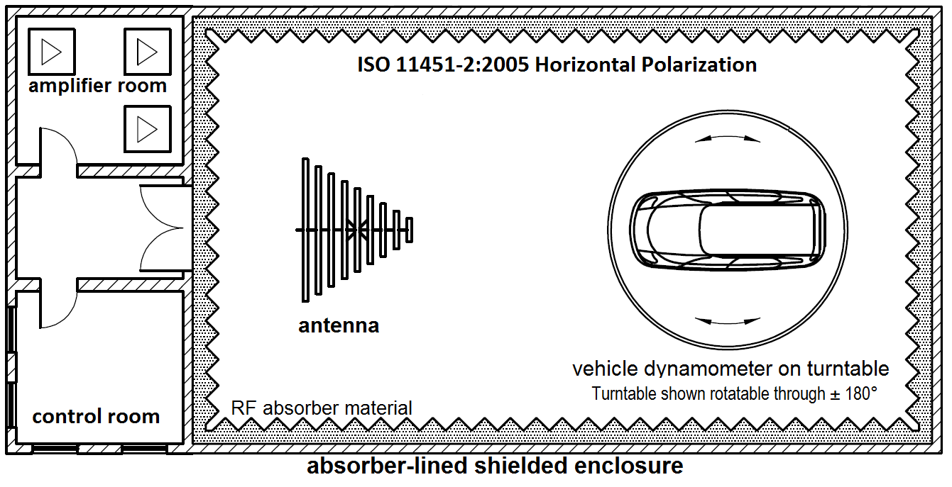
NB RF Immunity for EV should be carried out per IEC 61980-1 Annex B - Radiated RF Field 20 MHz - 2 GHz @ 30V/m using the test setup per ISO-11451-2:2005.
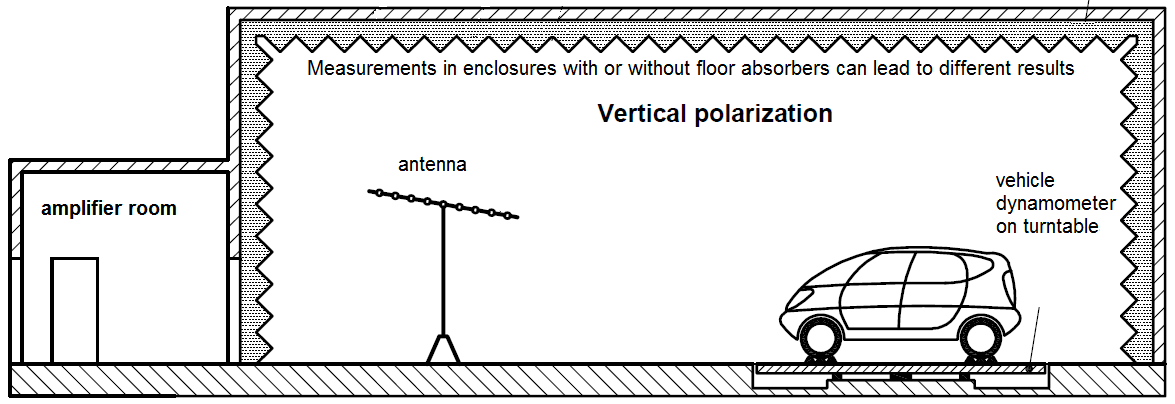
The test is performed in ALSE chamber, the aim being to create an indoor electromagnetic compatibility testing facility that simulates open field testing.
The position or positions of the vehicle relative to the antenna or TLS (Transmission Line System) are specified in the EMC test plan.
The radiating elements of the field-generating device is no closer than 0,5 m to any absorbing material and no closer than 1,5 m to the wall of the shielded enclosure.
No part of the radiating antenna is closer than 0,5 m to the outer body surface of the vehicle. The phase centre of the antenna is separated by at least 2 m horizontally from the reference point. No part of an antenna's radiating elements is closer than 0,25 m to the floor. There is no absorber material in the direct path between the transmitting antenna and the DUT.
No part of a TLS, with the exception of the ground plane, is closer than 0,5 m to any part of the vehicle. The TLS radiating element or elements is separated by at least 1 m vertically from the reference point. The TLS is extend centrally over at least 75 % of the length of the vehicle.
The test is performed using the substitution method, which is based on the use of forward power as the reference parameter used for field calibration and during testing.
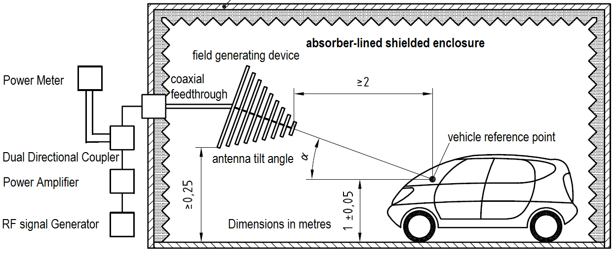
The field calibration is done without the vehicle present. The specific test level (field) shall be calibrated periodically, using an unmodulated sinusoidal wave, by recording the forward power required to produce a specific field strength (measured with a field probe) for each test frequency. The field strength is calibrated for vertical and horizontal polarizations.
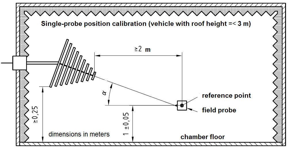
* at a height of (1 ± 0,05) m above the shielded enclosure floor for vehicles with a roof height =< 3 m;
* at a height of (2 ± 0,05) m for vehicles with roof heights > 3 m.
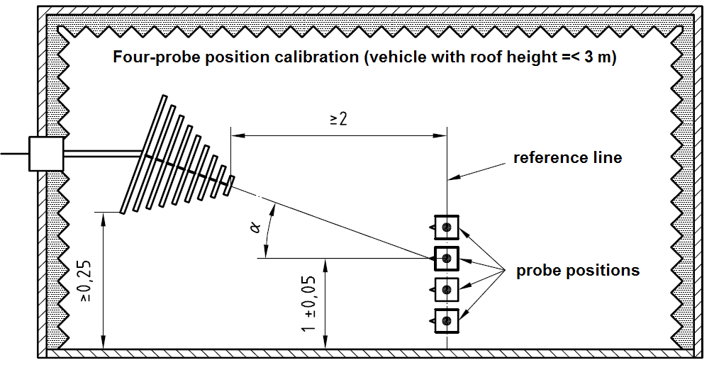
* at heights of 0,5 m, 0,8 m, 1 m and 1,2 m, for vehicles with a roof height =< 3 m;
* at heights of 1,2 m, 1,5 m, 1,8 m and 2,1 m, for vehicles with a roof height > 3 m.
8. June 2015 11:45 by streng in
Currently the WPT transfer distance is in range of several centimeters. Among the technical challenges to overcome we can mention:
- acceptable power transfer efficiency at high transfer range
- increasing power level
- misalignment tolerance
- safety considerations
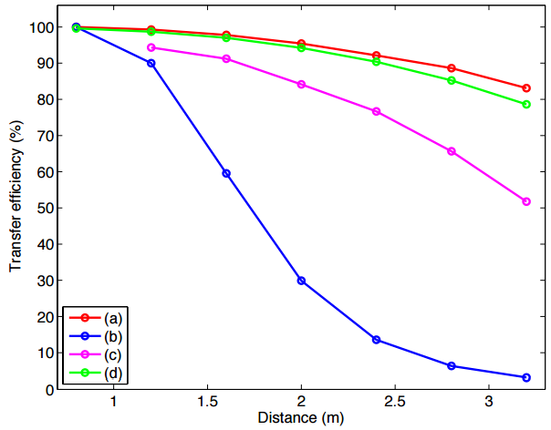
Coil-to-coil distance & 30 m working wavelength transfer efficiencies
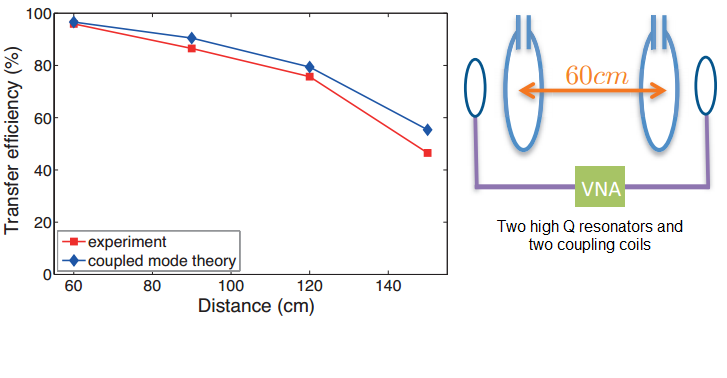
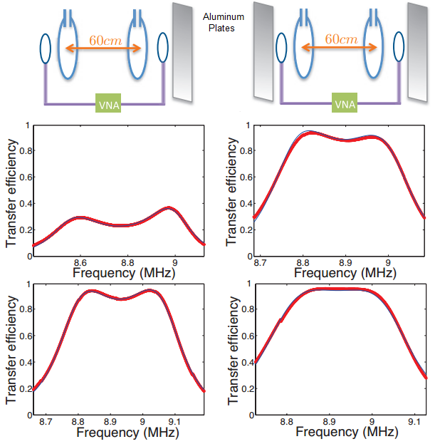
2-turn copper ribbon coil (3cm wide, 0.14 mm thick) with d=60cm and 5 to 70 pF adjustable high voltage capacitor. The quality factor of the resonator is 1338 in the absence of the metallic plane and 1329 in the presence of a metallic plane.
Source: Safe Wireless Power Transfer to Moving Vehicles: Design of Radiationless Antenna