FMC1278R3 specification mention that CI 280 (ESD Test Methods) must be carried out prior to any other test methods. If CI 280 fails, continuing the rest of EMC validation must be decided by FORD. The same 2 samples must theoretically withstand all FMC1278R3 test methods selected by EMC Test Plan.
The order of the test methods is critical, and the test results listed by laboratory report applies only to the two samples provided (Part Number, Serial Number, HW/SW revision). Some Europeans & Japanes automotive makers allow the use of multiple groups of samples to be used for simultaneously running test methods, probably to to speed up the completion of validation. This means that no sample is exposed to the full validation test list leaving room for insufficient EMC compliance evaluations.
Example of potentially destructive test methods:
- ESD on the first group of samples.
- Transients on supply lines on a second group of samples.
- Reverse Polarity on a third grtoup of samples
To compensate somehow such selective test methods allocation, the EMC Test Plan authors would require 3 samples per group instead of 2 samples per full validation.
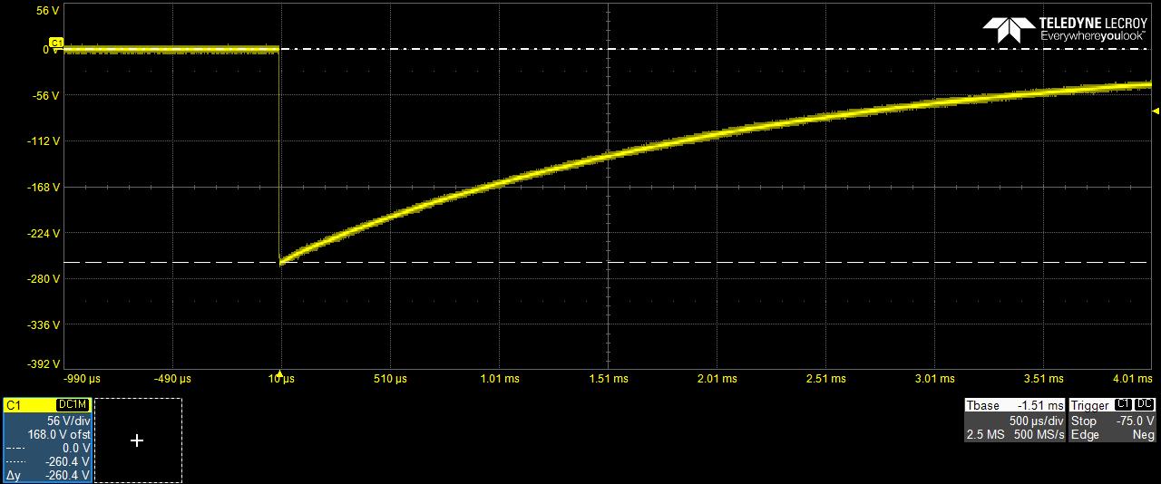
A parametric test is required following each immunity test method, and this may reveal some tolerances being pushed to one extreme if not outside the acceptable range. In a real scenario, following ESD powered one unit out of three was measured with 12 KΩ impedance on B+ line versus 16 KΩ prior to test. Other than that everything was functional, the DUT current consumption was the same before and after ESD. Theoretically this unit survived ESD and based on EMC Test Plan was not supposed to be tested for Transients on Supply Lines. By mistake this unit was tested for JASO Pulse B-2 (-260V) and the outcome was "sample damged on the second pulse". This EMC test plan trick was used to hide a poor DUT design performance for Honda that otherwise would have never pass FMC1278R3 spec.

Christian Rosu, Nov 8, 2021.
ISO 7637-2 Pulse 1
Conducted Immunity to Transients on battery lines.
Pulse 1 (Us = -150V, Ri = 10Ω, td = 2 ms, tr = 1µs, t1 = ≥ 0.5s (repetition rate), t2 = 200 ms, t3 < 100µs) can upset functionality of electronic modules. Most automotive OEM specs are accepting Class B response (DUT self-recoverable deviations), others are asking Class A response (no deviations) during Pulse 1.
In this particular case the pass/fail criteria was Charging Voltage remains 5V ±0.5V for 12V Battery dropouts ≤ 500µs. The EMC test plan asked the use of DMM to monitor the USB charging function for a Class A expected response:
- This was a simulation of a mobile phone charging event.
- DMM can only detect 5V Charging Voltage dips/drops ≥ 250 µs. A FLUKE can be set to count MAX and MIN voltage peaks, otherwise to monitor 5V fast voltage fluctuations is not practically possible.
- The EMC test plan allowed the use of oscilloscope only for information.
Download this movie to see how the charging function was monitored simultaneously on both oscilloscope and DMM:
5V_Charging_during_P1.mp4 (127.57 mb)
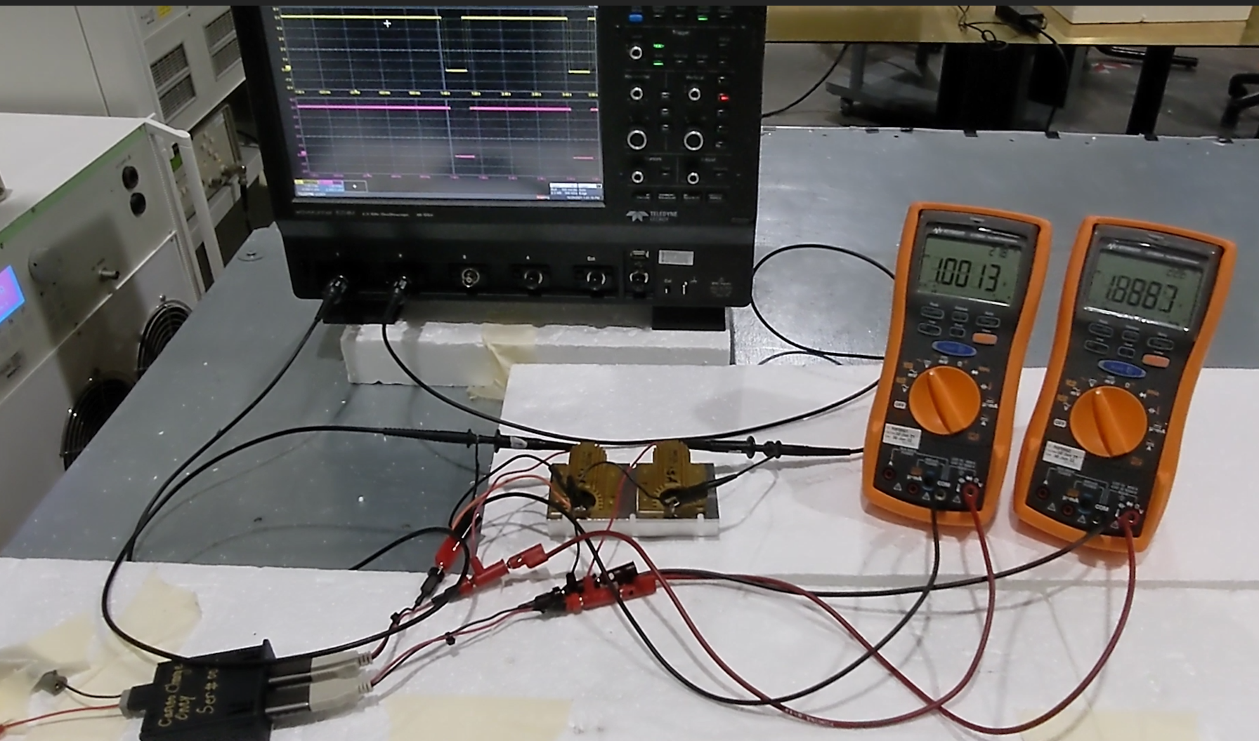
A similar monitoring equipment limitation was imposed the EMC Test Plan for dropouts test. Download this movie to see how the charging function was monitored simultaneously on both oscilloscope and DMM:
5V_Charging_during_500_microSec_dropout.mp4 (30.91 mb)
Christian Rosu, Nov 8, 2021
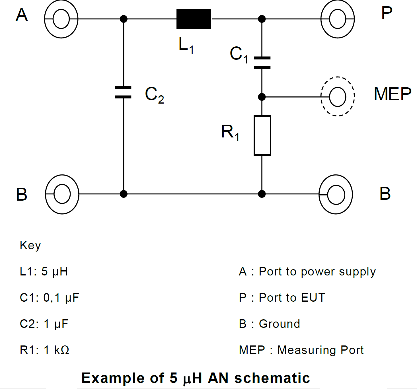
The latest revision of CISPR 25 is looking into various types of Artificial Networks used in today's automotive EMC.
1. Artificial Network (AN): used for LV power supplies;
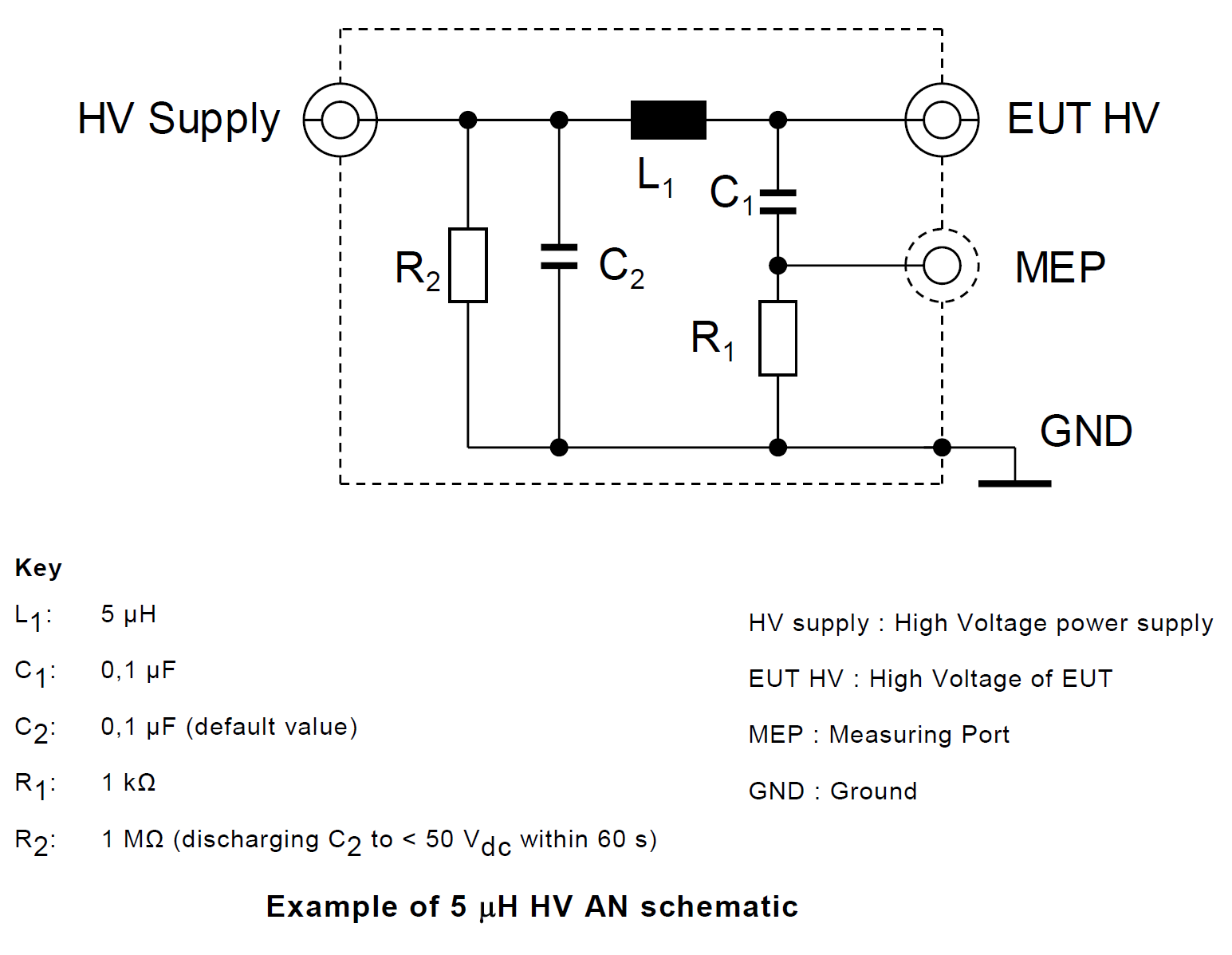
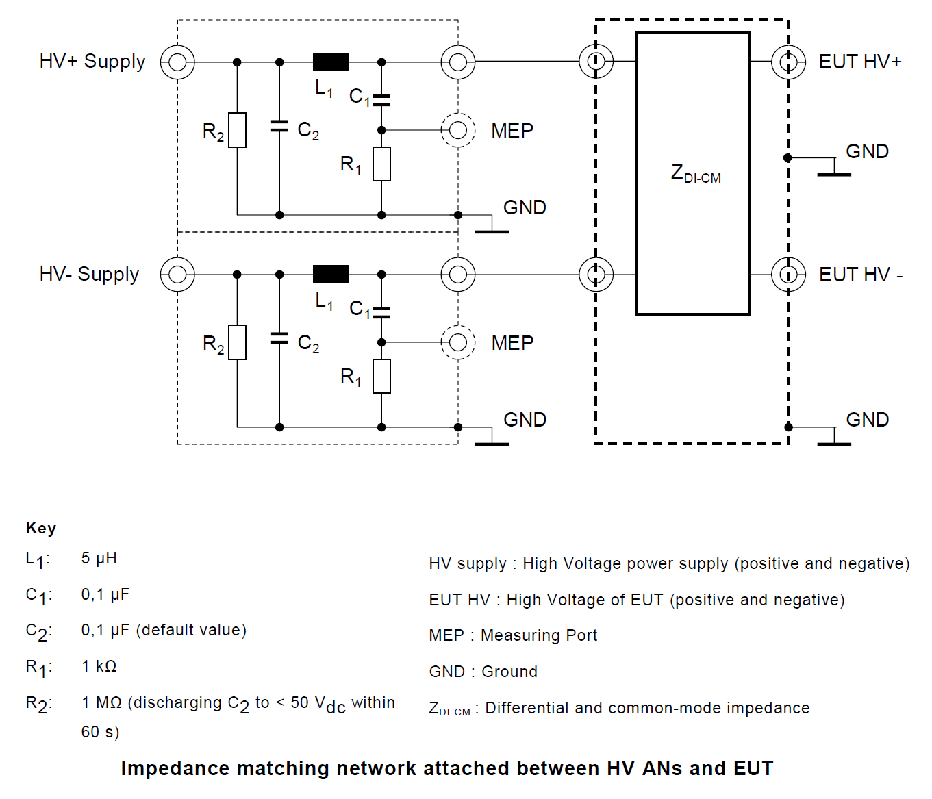
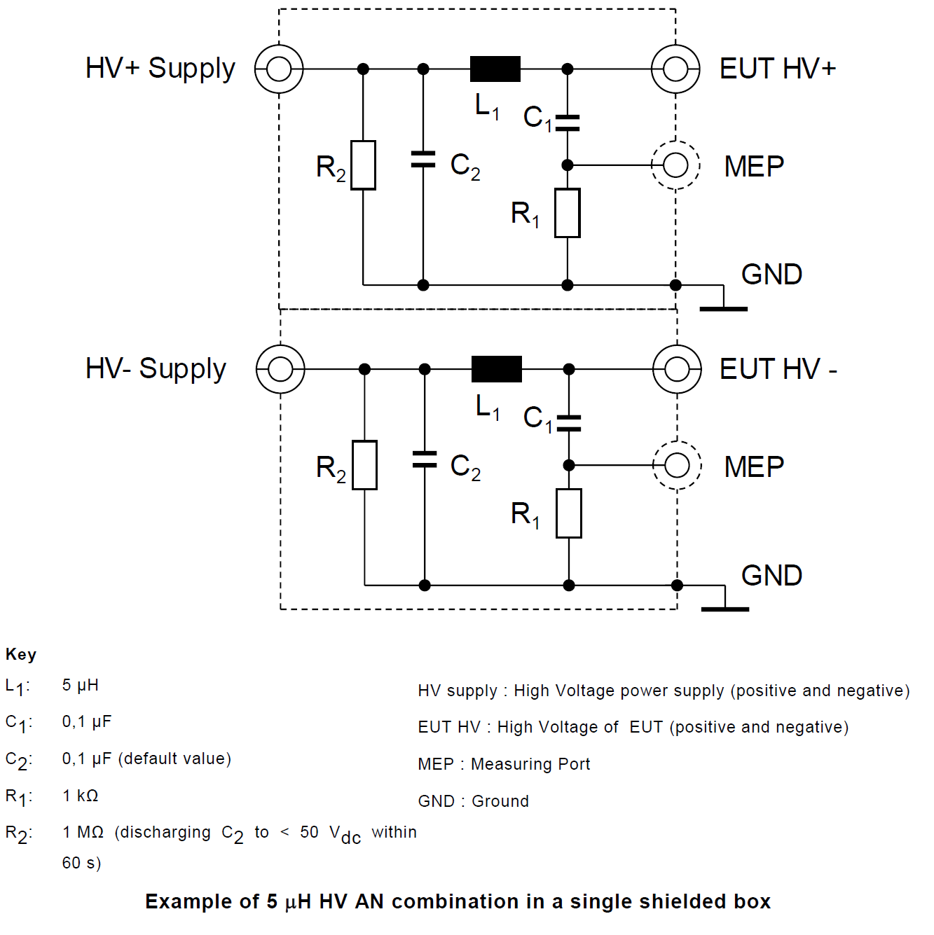
2. High Voltage Artificial Network (HV-AN): used for high voltage d.c. power supplies;
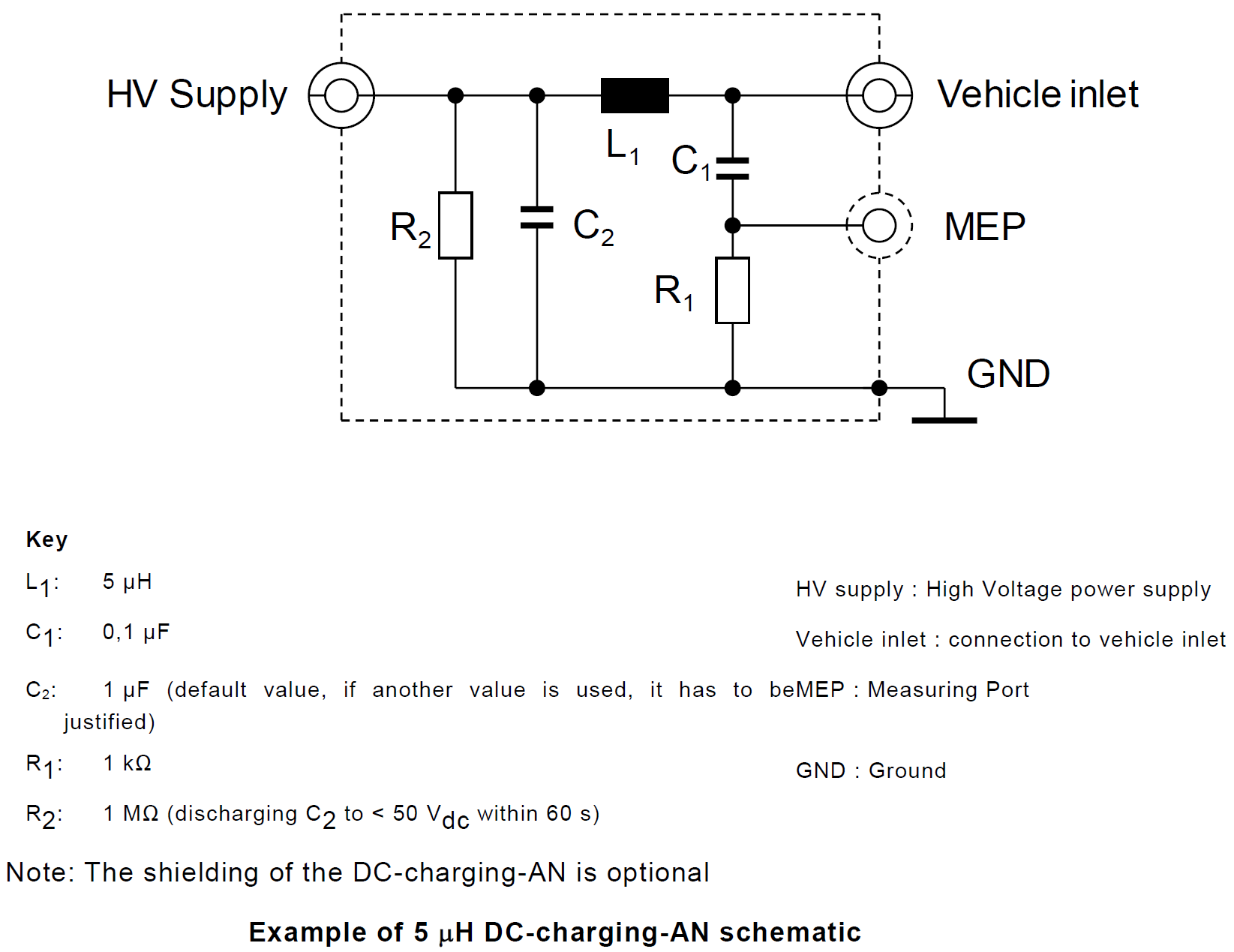
3. Direct Current charging Artificial Network (DC-charging-AN): used for d.c. power supplies;
4. Artificial Mains Network (AMN): used for a.c. power mains;
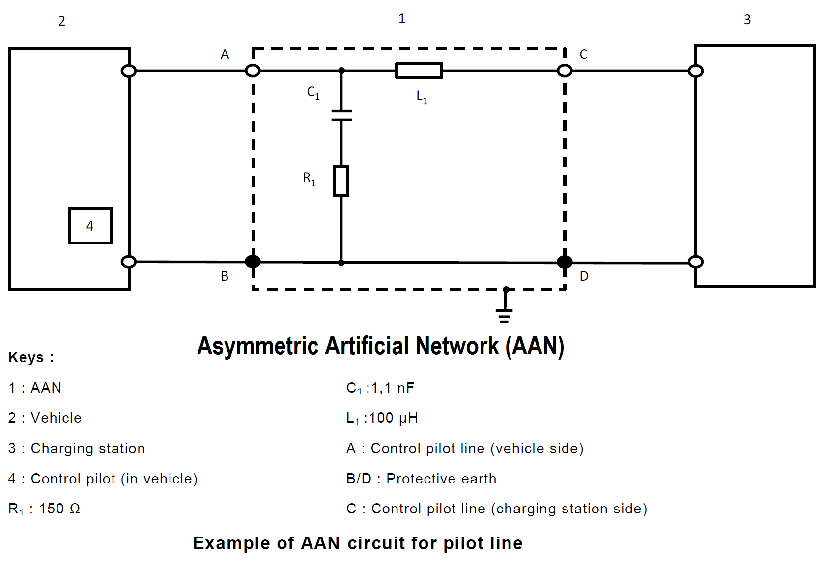
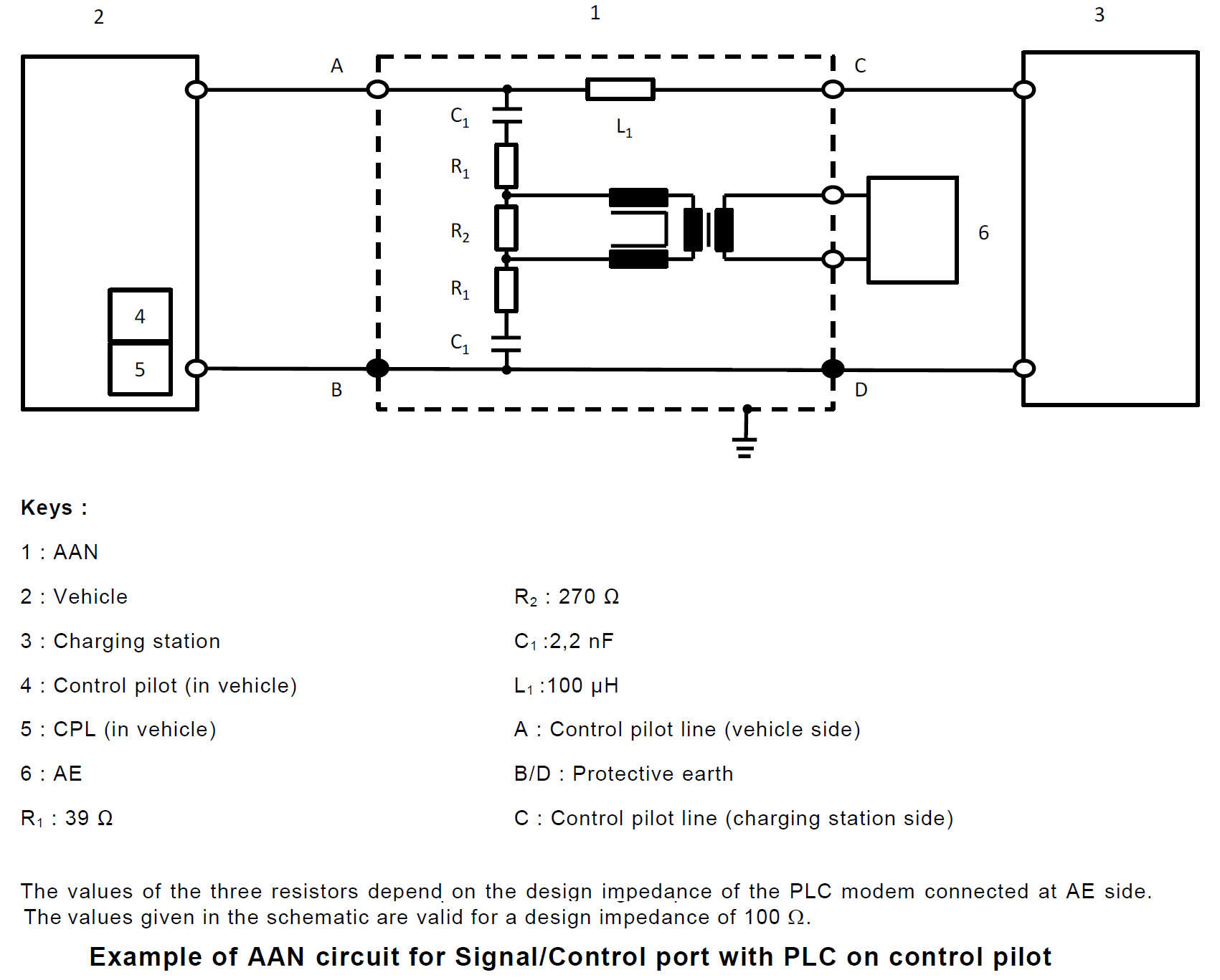
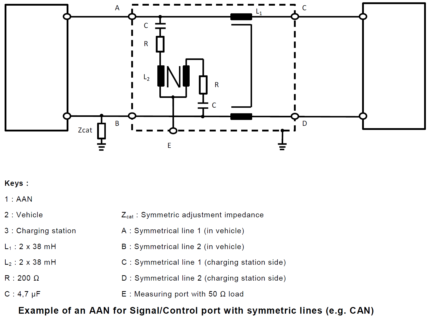
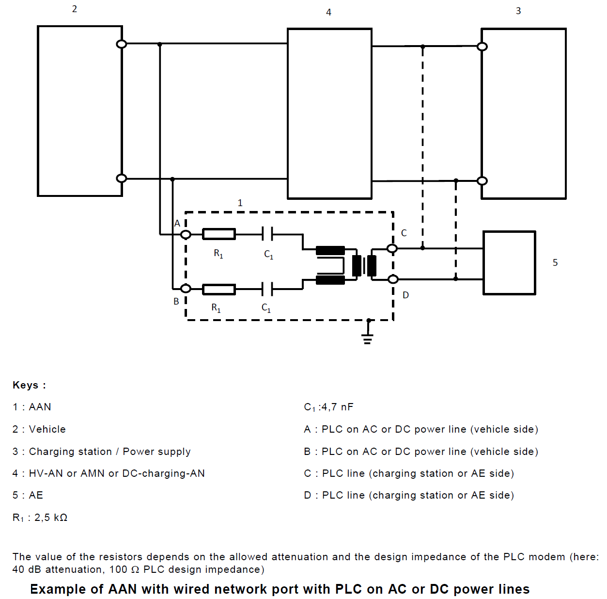
5. Asymmetric Artificial Network (AAN): used for signal/control port lines and/or wired network port lines.
1. Artificial Network (AN)
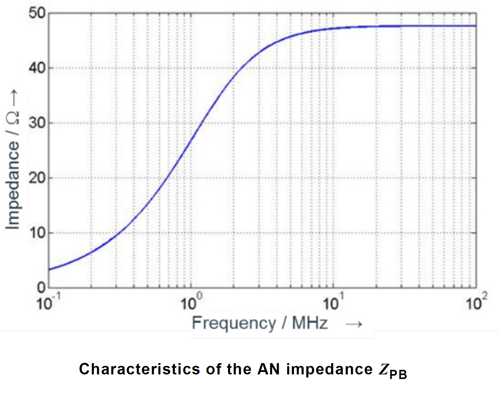
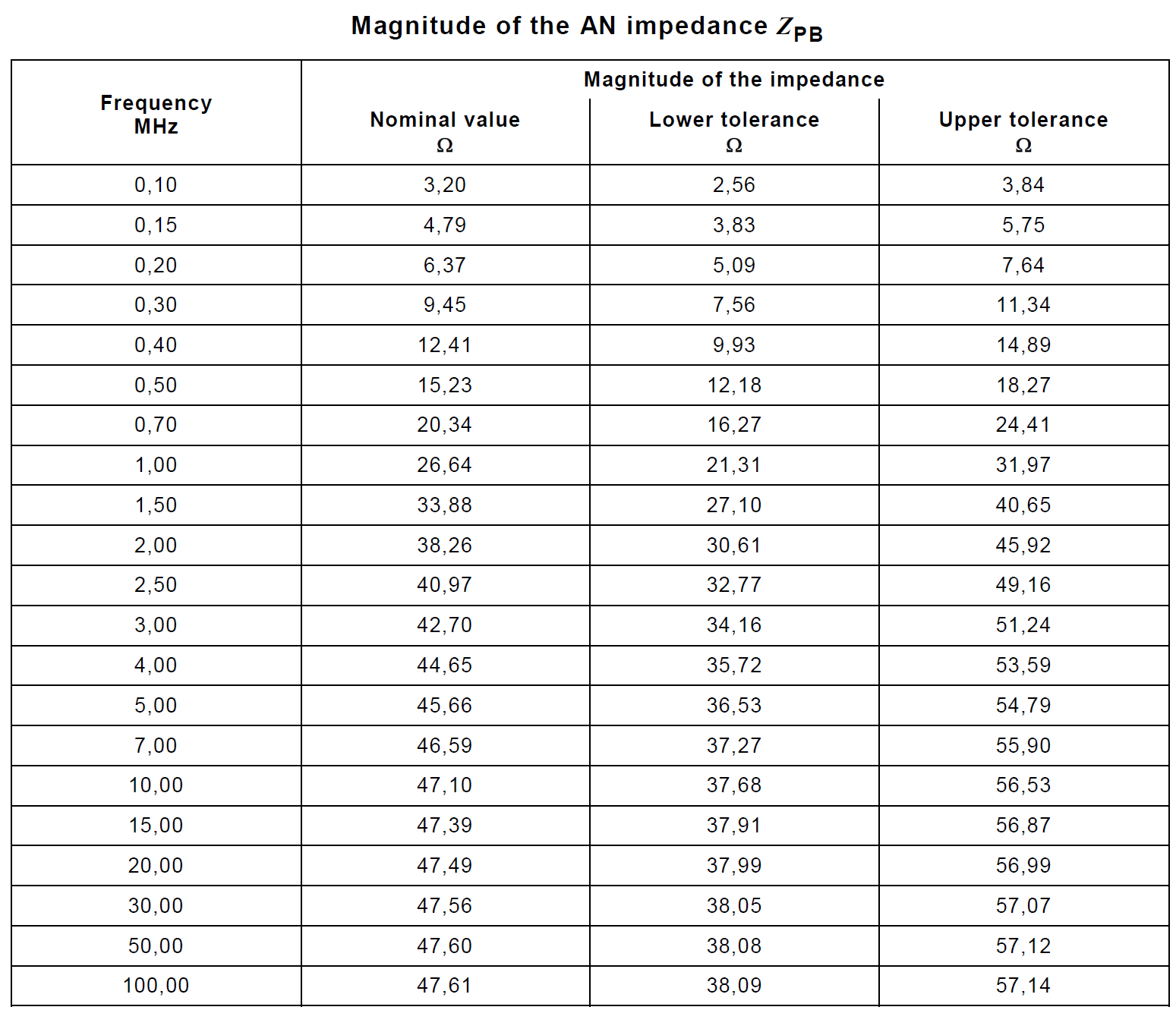
Measurement ports of HV-AN(s) must be terminated with a 50 Ω load. The HV-AN impedance ZPB (tolerance ± 20 %) in the measurement frequency range of 0.1 MHz to 100 MHz. This table above shows the nominal impedance and upper/lower tolerances in tabular form. It is measured between the EUT HV and ground terminals with a 50 Ω load on the measurement port and with the supply line HV and ground terminals short circuited.
2. High Voltage Artificial Network (HV-AN)
3. Direct Current charging Artificial Network (DC-charging-AN)
4. Artificial Mains Network (AMN)
Power mains must be applied to the vehicle through 50 μH/50 Ω AMN(s). The DC resistance between the ground of the AMN measurement port and the ground plane must not exceed 2,5 mΩ.
5. Asymmetric Artificial Network (AAN)
Christian Rosu
2021-06-22
An incorrect DUT grounding scheme can easily make the difference between compliance and non-compliance to CISPR 25 CEI limits. Sometimes we have to evaluate CEI from two modules, one used as DUT and the other one used as DUT's load (e.g. Module #1 is a PWM maker while Module #2 is an LEDs Lamp).
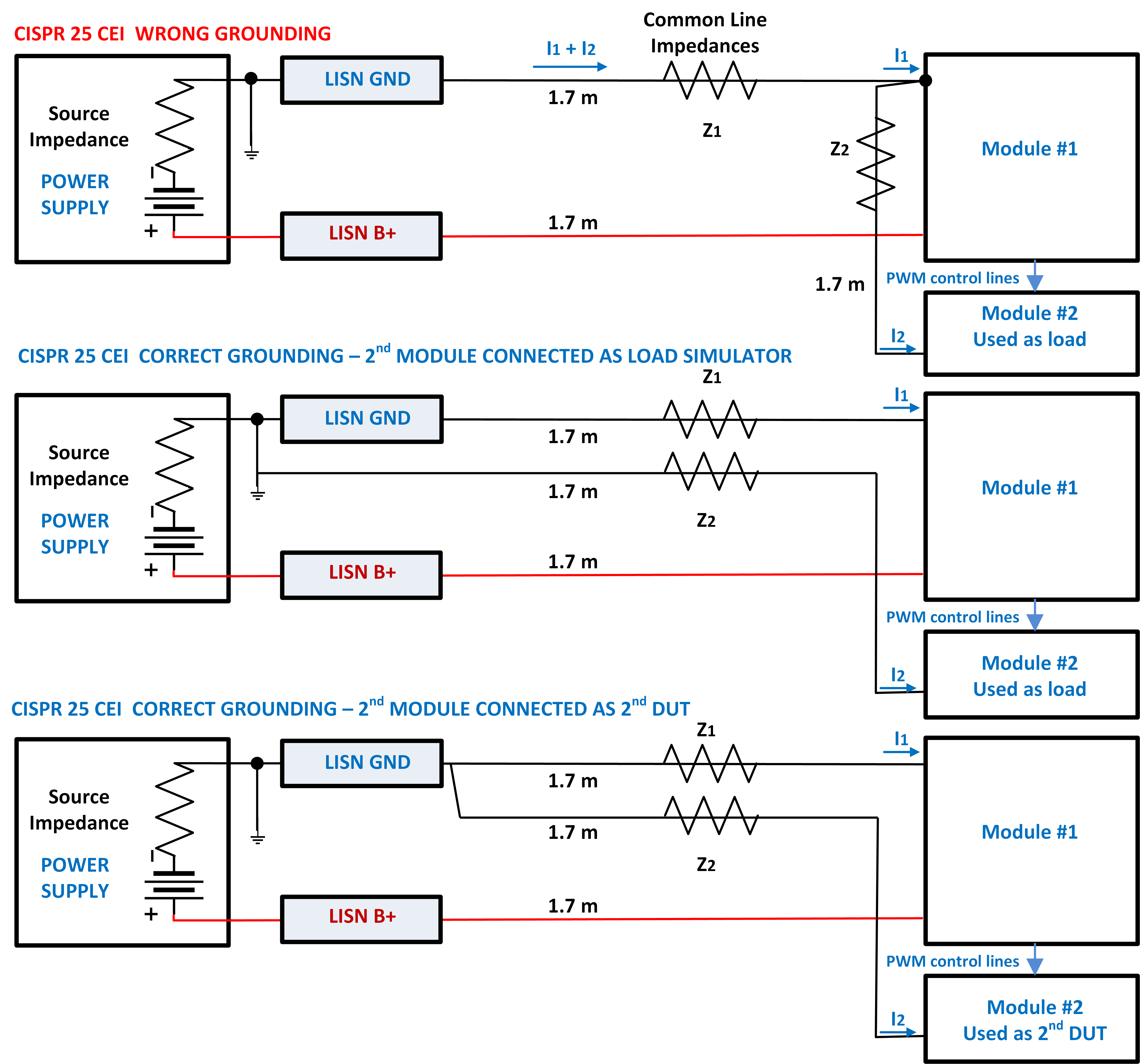
Christian Rosu, 2021-06-09
20. April 2021 22:08 by Christian in
EMC/EMI, EMC TEST PLAN One common mistake in EMC Test Plans is to associate Pass/Fail criteria with DUT Operating Modes.
For Operating Modes it is critical to define how DUT's:
1) Load Simulator & Support Equipment is configured.
2) Functions are activated.
3) Behavior is monitored.
4) data is collected and reported.
Defining Pass/Fail Criteria for a particular Operating Mode maybe in conflict with requirements listed by automotive OEM EMC spec or standard. The DUT performance and response behavior will always vary depending on the Test Method.
Based on Functional Status Classification the Pass/Fail Criteria must be specified for each Test Method while the DUT is activated in a particular Operating Mode.
For example, ISO 7637-2 Pulse #1 (t2 is 0V for 200 ms). I doubt that an E-Net port won’t miss data packets generating bit errors under such circumstances. Depending on the Test Method and required immunity severity level the EMC spec/standard would allow certain self-recoverable DUT anomalies. Since the EMC Test Plan can override the EMC spec requirement would be a mistake to mention something like "no loss of E-Net data packets" as pass criteria for "DUT Operating Mode #1". This would imply that loosing one packet of data during Pulse #1 the DUT "fails" when in fact the EMC spec would allow it:
"One or more functions of the DUT can go beyond specified tolerance provided that all functions return within normal limits after the exposure is removed (e.g., after UA power is re-applied after the 200 ms defined by t2 as defined in ISO 7637-2). No damage or degradation of memory functions is permitted."