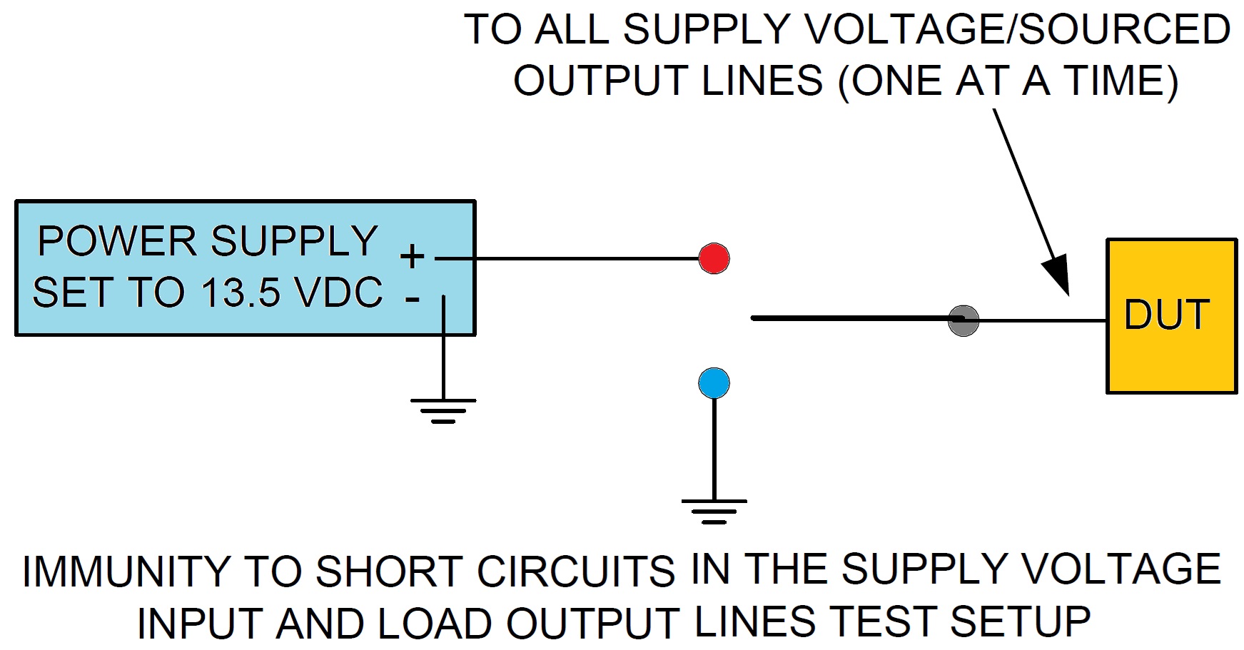
1. Immunity to Short Circuits in the Supply Voltage Input and Load Output Lines
- Using 13.5 Volts on all supply lines, verify proper DUT operation.
- Connect a power supply to one supply line or load output line, set it for 13.5 volts. Then, switch it from the 13.5 volts to ground for 5 seconds.
- Repeat the above process for all supply lines and load output lines verifying proper operation each time.
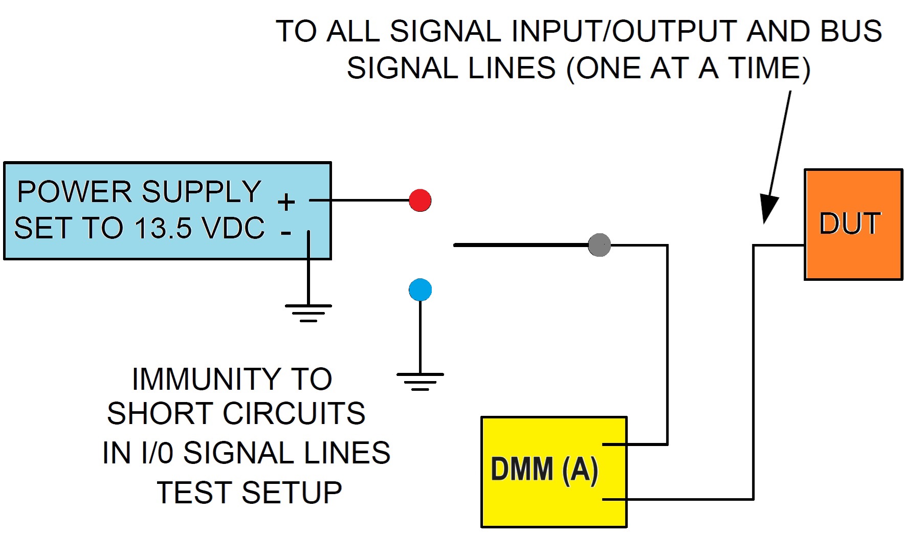
2. Immunity to Short Circuits in I/O Signal Lines
- Using 13.5 Volts on all supply lines, verify proper DUT operation.
- Connect a power supply to one I/O line, set it for 13.5 volts.
- Record the steady state current. Then, switch from the 13.5 volts to ground.
- Repeat the above process for all I/O lines verifying proper operation each time.
- Unless the test plan specifies otherwise, maximum steady state current recorded shall be less than 200 mA.
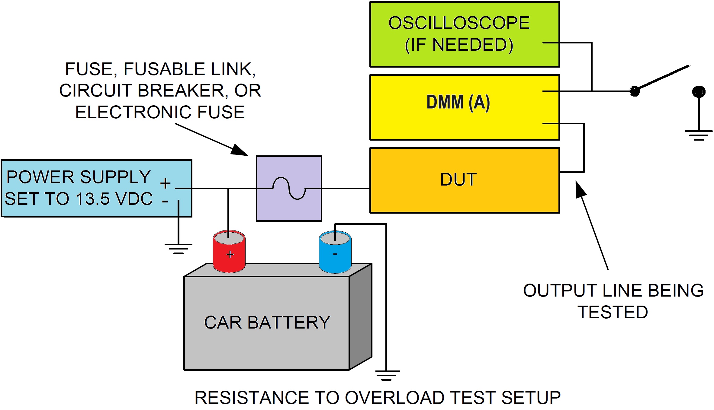
3. Resistance to Overload
- Fuses/Fusible Links/Circuit Breakers - short the output line to ground using the switch and measure both the current and time needed to open the circuit protection device. The current and time values and limits shall be given in the test plan. If no circuit protection device is used the DUT shall withstand a short circuit to ground for five minutes without damage to the DUT.
- Electronic Breakers - short the output line to ground using the switch and measure both the current and the time needed to open the circuit protection device. Verify proper operation of the Electronic Breaker and DUT per test plan.
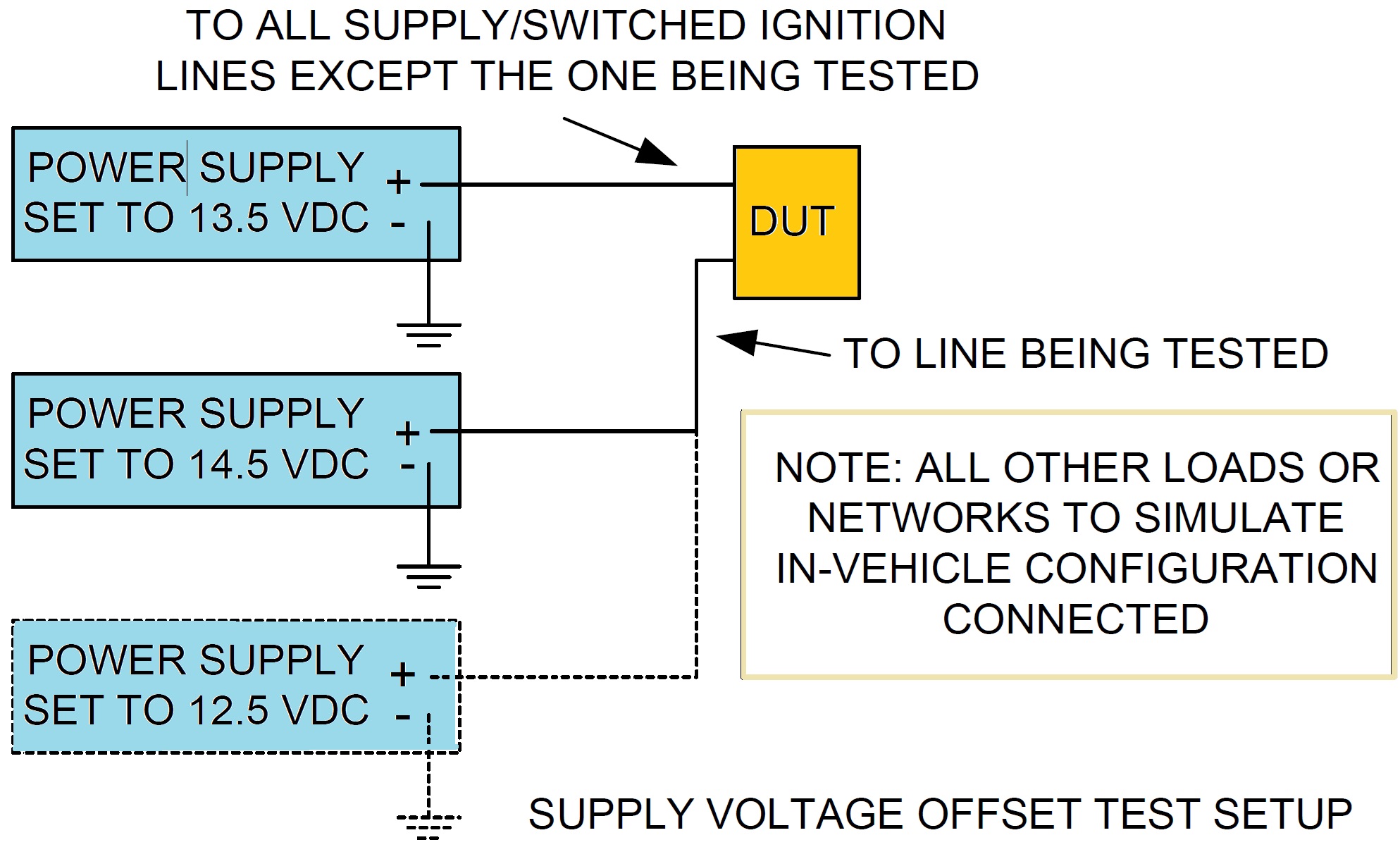
4. Supply Voltage Offset
- Using 13.5 Volts on all supply lines, verify proper DUT operation.
- Connect a power supply to one supply line, set it for 14.5 volts, and verify proper DUT operation. Repeat for 12.5 volts.
- Repeat the above two steps for all battery and switched ignition supply lines in any combination.
- Repeat entire procedure two more times for a total of three complete measurement cycles.
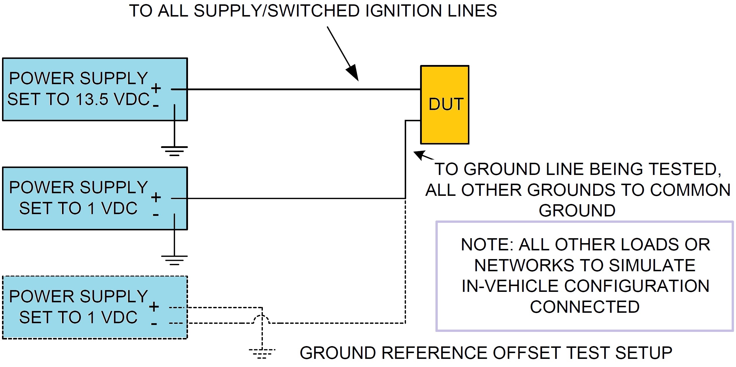
5. Ground Reference Offset
- Apply a 13.5 Volt supply voltage to the DUT and verify proper operation.
- Connect a power supply to one ground line, set it for 1 volt, and verify proper DUT operation.
- Repeat for –1 volt.
- Repeat the above two steps for all ground paths in any combination.
- Repeat entire procedure two more times for a total of three complete measurement cycles.
Christian Rosu
