EMC FLEX BLOG A site dedicated to Automotive EMC Testing for Electronic Modules

Switching to an electric car turns the environemnet green only in certain countries

17. September 2015 09:31 by Christian in
The carbon emissions from electricity generation are measured in tones of CO2 emitted per gigawatt h

The carbon emissions from electricity generation are measured in tones of CO2 emitted per gigawatt hour of electricity produced.

  • tCO2e/GWh = 0 for hydroelectric, nuclear and renewable energy
  • tCO2e/GWh = 500 to 600 for natural gas power plants
  • tCO2e/GWh = 1000 for coal-fired power plants

In countries that generate much of their electricity by burning coal charging EV's battery will significantly boosts carbon emissions. Even in Canadian provinces Alberta, Saskatchewan and Nova Scotia, electric cars generate more carbon pollution over their lifetimes than gas-powered cars. To really contribute to a greener environment you have to buy rather an HEV than EV. Sources


Christian Rosu

LISN (Line Impedance Stabilization Network) or AN (Artificial Network)

14. September 2015 14:29 by Christian in EMC/EMI, Standards, Test Equipment
Purpose of the LISN:1. Provide well defined RF impedance to the DUT.2. The 1μF & 50μH filt

Purpose of the LISN:
1. Provide well defined RF impedance to the DUT.
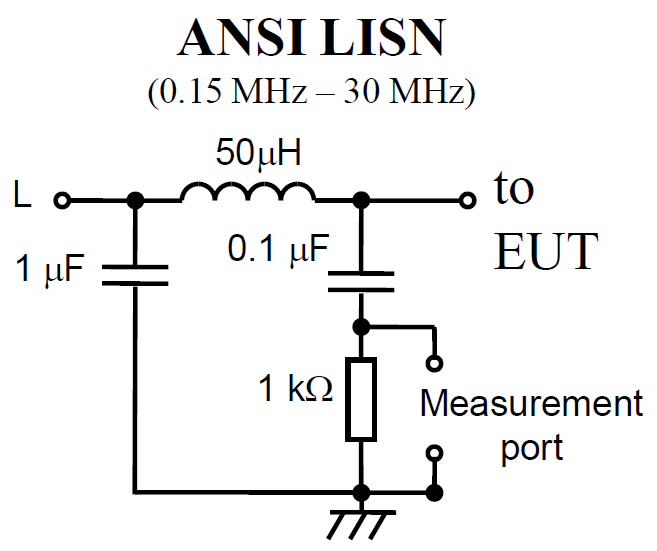
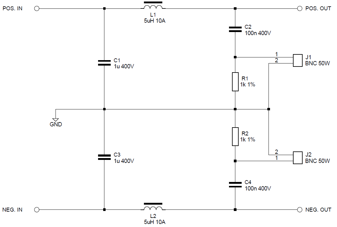
2. The 1μF & 50μH filter isolates the noise that is put on the supply lines by DUT from feeding back to the power supply / battery.
3. Provide a low impedance path for the noise to be measured at the output port of the LISN coupling the interference voltage generated by DUT via 0.1μF to the analyzer or receiver.

The role of the LISN is to isolate the DM current and CM current from the power supply, and to minimize the impact of the CM current by returning it to its sources.

The wire harness inductance for large systems (aircraft) is 50μH whereas for small systems (automotive) is 5μH. However, the LISN selection criteria should be based on the frequencies of the measurements required.
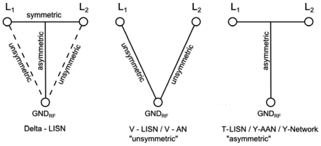
     

Types of LISN

  1. V-LISN: Unsymmetrical emissions (line-to-ground)
  2. Delta-LISN: Symmetric emissions (line-to-line)
  3. T-LISN: Asymmetric emissions (mid point line-to-line)


There are two types of V-LISN with different impedances.

  • 5 µH inductance (CISPR 16-1-2, CISPR 25, ISO 7637, SAE J1113-41, DO160) are normally used to measure equipment for vehicles, boats and aircrafts connected to on-boards mains with DC or 400 Hz.
  • 50 µH according to CISPR 16-1-2, MIL STD 461 and ANSI C63.4 is intended to operate at mains frequencies of 50 Hz or 60 Hz.

The T-LISN measures the asymmetric disturbance voltage (common mode voltage) and provides it to an EMI Receiver. It is normally used for measuring telecommunication and data transmission equipment connected to symmetrical lines as e.g. twisted pairs.

CISPR-25 (Ed 3.0)
A network inserted in the supply lead or signal/load lead of apparatus to be tested which provides, in a given frequency range, a specified load impedance for the measurement of disturbance voltages and which may isolate the apparatus from the supply or signal sources/loads in that frequency range.
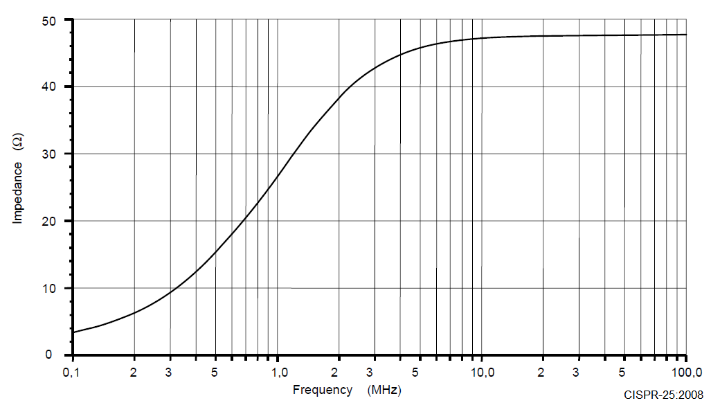
CISPR-25 (Ed 3.0) & ISO-11452-2:2004 & ISO-11452-4
The AN impedance ZPB (tolerance ± 20 %) in the measurement frequency range of 0.1 MHz to 100 MHz it is measured between the terminals P and B with a 50 Ω load on the measurement port and with terminals A and B short-circuited.


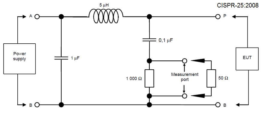
The 1μF capacitor is populated in CISPR-25 LISN; R=1Kohm.


ISO 7637-2:2011 & ISO-11452-2:2004 & ISO 7637-2:2004
The artificial network is used as a reference standard in the laboratory in place of the impedance of the vehicle wiring harness in order to determine the behavior of electrical/electronic devices.
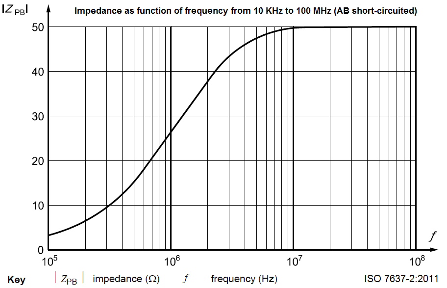
ISO 7637-2:2011 & ISO 7637-2:2004
The resulting values of impedance ZPB, measured between the terminals P and B while terminals A and B are short-circuited, are given in figure below as a function of frequency assuming ideal electric components. In reality, the impedance of an artificial network shall not deviate more than 10 % from the given curve.


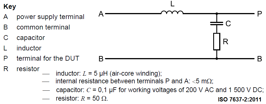
No 1μF populated in ISO 7637-2 LISN; R =50 ohm, C is function of voltage.


Sample setup: CISPR-25 require separate LISN for B+ and GND lines.

Christian Rosu

Electromagnetic Spectrum

13. September 2015 15:32 by Christian in Standards
Spectrum is a continuum of all electromagnetic waves (EM) traveling at constant speed (300,000 km/s)

Spectrum is a continuum of all electromagnetic waves (EM) traveling at constant speed (300,000 km/s). An electromagnetic wave consists of electric and magnetic fields which vibrates thus making waves. EM wave wavelength decreases as its frequency increases. Shorter the wavelength, higher is the EM wave energy. Waves with higher frequency can carry a higher energy. The energy is measured in Joules or Electron-Volt (1 J = 6.241509 *10^18 eV).

Wave speed is independent of frequency. Frequency has an inverse relationship to the wavelength, λ (lambda). Lambda * Frequency = Speed


Frequency Allocation Charts:

US: 2011_US_rf_spectrum_chart.pdf (334.3KB)

CANADA: 2014_Canadian_Radio_Spectrum_Chart.pdf (279.1KB)

UK: uk_frequency_allocations_chart.pdf (325.8KB)

AUSTRALIA: aust_rf_spectrum_allocations_chart.pdf (296.7KB)

IEC 61000-4-4 (Electric Fast Transients / Burst)

13. September 2015 14:28 by Christian in Test Methods
A burst arc occurs when a mechanical contact is open during the switching process.Burst sources:• Ci

A burst arc occurs when a mechanical contact is open during the switching process. Burst sources:
• Circuit Breakers in electrical circuits
• High Voltage switchgear
• 110/230V Power Supply systems
• 24V Control Lines

A burst has a single pulse rise time/duration of 5 ns / 50 ns from a 50 Ohm source impedance.
Bursts of 15 ms duration with a repetition rate of 5 kHz (or 100 kHz) are applied every 300 ms.

Voltage test levels:
• Power ports: 0.5 KV, 1 KV, 2 KV, 4 kV
• Signal and Control ports: 0.25 KV, 0.5 KV, 1 KV, 2 kV

• Coupling method is used to transfer the transient to the DUT.
• Decoupling method is used to block the transient from entering the mains and damaging other equipment connected in the network.

• Power line coupling is done with direct CDNs (Coupling/Decoupling Networks).
• Signal line coupling is done with a CCC (Capacitive Coupling Clamp): two metal plates which sandwich the line under test (cable) to provide a distributed coupling capacitance.

Test waveform verification is mandatory prior to each test.
For equipment connected to power ports all lines are coupled simultaneously.

Christian Rosu

Plug-in Electrical Vehicle - Residential Charging Time

13. September 2015 13:09 by Christian in
Installing residential EVSE (Electrical Vehicle Supply Equipment) in a garage for Level 2 charging m

Installing residential EVSE (Electrical Vehicle Supply Equipment) in a garage for Level 2 charging may require changes to the home’s electrical wiring and a permit from the local jurisdiction.