EMC FLEX BLOG A site dedicated to Automotive EMC Testing for Electronic Modules

Test Procedure vs Test Method in automotive electronics EMC testing

11. December 2020 13:13 by Administrator in EMC/EMI, OEM Specs, Standards, Test Methods
Differences between Test Procedures and Test Methods in automotive EMC/EMI vocabulary.

Test Procedure:

  • what the activity is (DUT type)
  • who is to perform the activity (EMC Testing Laboratory)
  • when the activity is to take place

This is more of an EMC Test Plan Template document that:

  • defines the DUT classification and category
  • lists required EMC Test Methods defined by the automotive OEM specs or International Standards (ISO, CISPR, SAE, etc.).


Test Method:

  • how  the actual EMC testing is to be carried out (test equipment configuration)
  • defines measurable data format for reporting and acceptable stress level limits 

This more of a Work Instruction outlined by automotive OEM EMC specs and international standards.

Christian Rosu, Dec 11, 2020.

DUT configuration for CISPR 25 ALSE chamber ambient

28. October 2020 07:03 by Christian in EMC/EMI, EMC TEST PLAN, OEM Specs, Standards, Test Methods
The automotive OEM specs do not specify how to configure the DUT during CISPR 25 chamber ambient measurements.

The automotive OEM specs do not specify how to configure the DUT during CISPR 25 chamber ambient measurements. DUT must be unpowered, all other DUT support equipment must be powered and as much as possible functional to correctly evaluate RF emissions noise floor before start testing. This leaves at least three scenarios for how to configure the DUT.

 
1) Disconnect the DUT from test harness. 
  1.  Test harness connectors are removed from
  2.  DUT is unpowered.
  3.  The 1.7 m test harness is unterminated on DUT side, no potential ground loops with Load Simulator.
  4.  The 5uH LISN remains present.
  5.  The Load Simulator and all support equipment remains powered.
 
2) Disconnect DUT's B+ line from LISN output.
  1.  Test harness connectors are plugged into DUT.
  2.  DUT is unpowered by disconnecting B+ line LISN input from Battery.
  3.  The 1.7 m test harness terminated on both ends, therefore potential ground loops with Load Simulator are possible.
  4.  The 5uH LISN remains present.
  5.  The Load Simulator and all support equipment remains powered.
 
3) Diconnect DUT's B+ line from LISN output.
  1.  Test harness connectors are plugged into DUT.
  2.  DUT is unpowered by disconnecting DUT B+ line from LISN output.
  3.  The 1.7 m test harness terminated on both ends, therefore potential ground loops with Load Simulator are possible.
  4.  The 5uH LISN is not present anymore, and this somehow violates CISPR 25 requirement.
  5.  The Load Simulator and all support equipment remains powered.
 
Christian Rosu

CISPR-25 RF emissions ambient test pitfalls

25. April 2017 15:48 by Christian in EMC/EMI, EMC TEST PLAN, Standards
CISPR-25 is not very specific in regards to chamber ambient test setup configuration in regards to d

CISPR-25 is not very specific about device under test and support equipment configuration during chamber ambient test. The automotive OEM require the ambient for RE, CE-V, CE-I with support equipment energized. The test laboratories will typically disconnect VBATT line from LISN output. The GND line remains connected to LISN. By doing so is assumed that DUT is not energized. The support equipment remains connected to the input of the LISNs being turned on (energized). The CAN bus is powered but w/o traffic. It is unclear if the load simulator energized it means powered but inactive (standby). By activating PWM pulses as inputs for DUT it may yield unwanted CE-I and RE ambient noise. All these aspects must be clarified in the EMC test plan.

In the sample presented the CE-V ambient noise is well below the 6 dB requirement. However, this type of noise is being captured while DUT's integrated buttons are being pressed and released via a pneumatic system with no electrical connection to DUT or test ground plane. Specifying that DUT must be unpowered may not be enough, the DUT's buttons should not be mechanically activated, nor its inputs subjected to electrical signals.

 
Christian Rosu

Automotive Centralized Load Dump Test Requirements

15. September 2016 23:42 by Christian in OEM Specs, Standards, Test Methods
Types of load dump transient generators and suppressed load dump pulse

Types of load dump transient generators

The high energy content of load dump pulse require specialized pulse generators like classic LCR or DC amplifier based pulse generators.

The LD pulse width and amplitude decrease the smaller the connected load gets. Such requirement can only be fulfilled by using a generator using an energy storage capacitor and a passive pulse-forming network.
Using a programmable DC amplifier to generate LD then pulse amplitude can be set correctly but can't adjust the pulse duration. The DC amplifier based generator outputs considerably more energy being applied to the DUT, which increases the chances to see DUT false deviations.
Curve #1 is unsuppressed LD using generator per ISO 7637-2:2004 Annex E (energy capacitor based LD generator)
Curve #2 is unsuppressed LD using DC amplifier
Curve #3 is suppressed LD using generator per ISO 7637-2:2004 Annex E (energy capacitor based LD generator)
Curve #4 is suppressed LD using DC amplifier
The white area shows the energy absorbed by a varistor or TVS representing the input protection of the DUT.
The grey areas indicate the energy that the DUT is actually exposed to during this test.
The sample above shows 70% higher energy being applied to the DUT by an amplifier based generator compared to the energy generated by an energy capacitor based generator.
 
ISO 7637-2:2004 ANNEX-E (Recommended Pulse Generator Type)

E.1 Determination and verification of pulse generator minimum energy capability
E.1.1 Calculation method

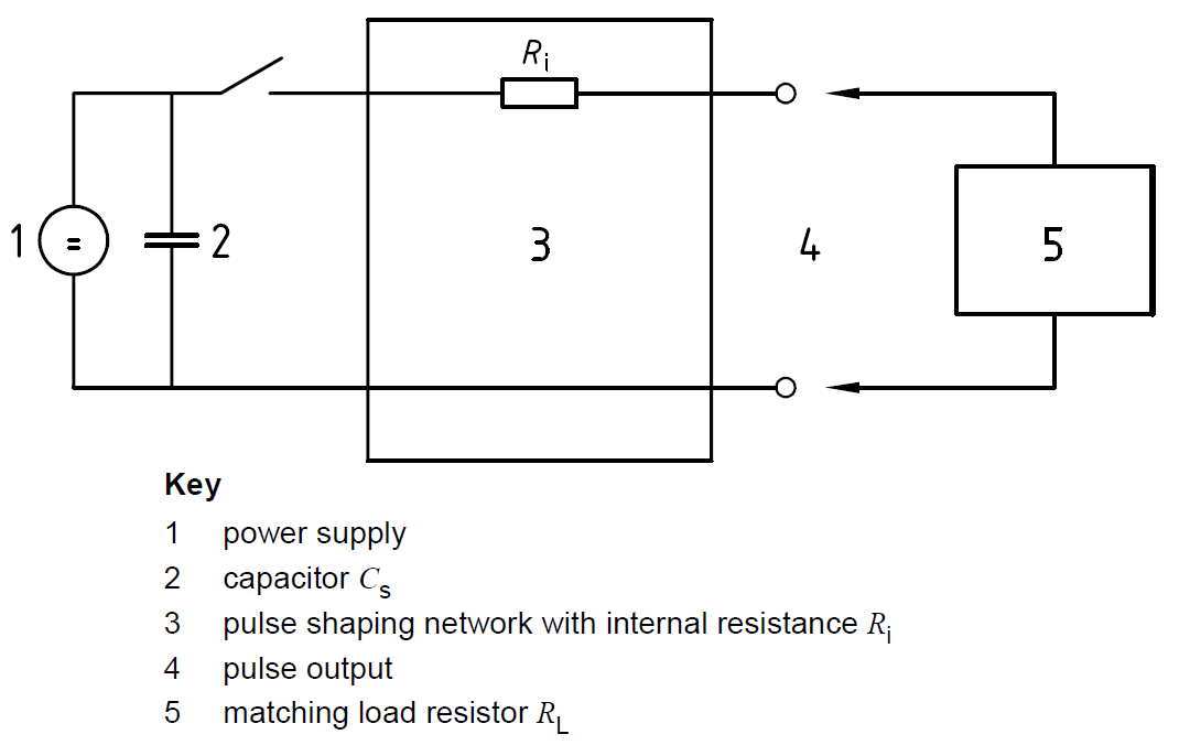
This method is used to calculate the energy of the pulse as delivered by the generator to the matching resistor (resistive load RL ), utilizing the measured pulse parameters td and Us.
The transient generator used shall generate double exponential transients, which are a result of capacitive discharges into a pulse shaping network. This type of generator is applicable to pulses 1 (12 V), 1 (24 V), 2a, 3a/3b and 5.

 
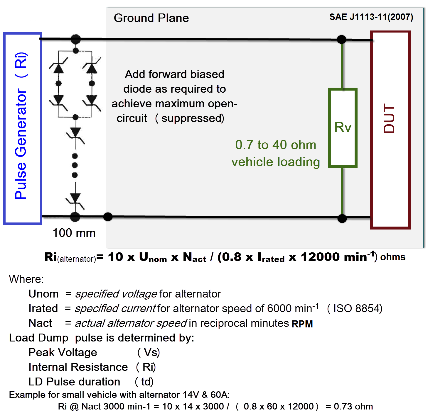
Alternator Load Dump Suppressor
During the LOAD DUMP the difference between two phases reaches up the breakdown voltage of the diodes and then they act as clamping parts. As the difference of potential between each phase is alternative then D1, D2, D3, D4, D5 and D6 act in clamping mode as well as in forward bias.
 
 
Centralized Load Dump Suppression
The vehicle central transient suppression device is connected directly across the main power supply w/o load resistance. It must absorb the entire load dump energy, and also withstand the full jump-start voltage. It is usually located in the most critical electronic module, however additional suppressors may be placed on other modules to further suppression and to control locally-generated transients.

SAE J1113-11 (2007)
The Load Dump Pulse Suppressed or Unsuppressed  is defined regardless to specification used by (Us) Peak Voltage in Volts, (Ri) Internal Resistance in ohms, and (td) Duration in ms.


The precise characteristics of suppressed load dump pulse varies based on automotive OEM type of centralized LD suppressor used. The testing methodology is periodically adjusted to accommodate new type of electronic devices. As of today most OEM specifications tend to relay on ISO 16750 for Load Dump.
 
GM9105P Pulse#6 (LD)
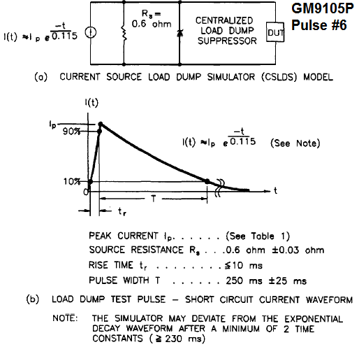
 
GMW3097(2015)
For pulse 5b, use 2 Ω as the source resistance (Ri) per ISO 16750-2. (Us = 34 V +0/-1 V)

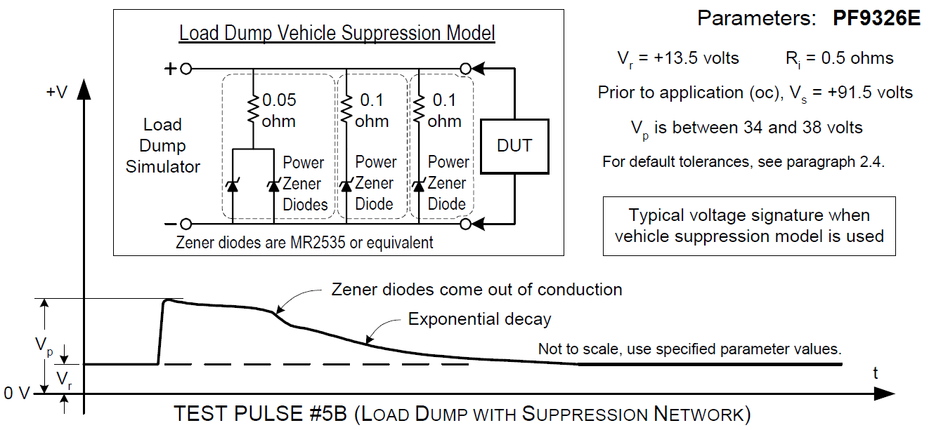
Load Dump Vehicle Suppression Model (PF9326E)
Case #1
  • DUT that operate in a vehicle using avalanche/zener diodes in the alternator for LD protection
    • suppressed LD must be clamped to the avalanche diode clamp level.
  • DUT that provide vehicle LD protection must be tested to verify
    • the peak current sinking capability
    • the clamping voltage under load
  • DUT expected to sink greater than 40 amps peak current (e.g., engine controller)
    • tested with an additional 1 ohm of resistance in series with the simulator.
  • DUT expected to sink greater than 25 amps peak current (e.g.,airbag control module)
    • tested with an additional 2 ohms of resistance in series with the simulator.
  • For both cases
    • the clamping voltage under load, across the DUT, must be less than 40 volts
  • For all other DUT
    • open circuit pulse is clamped to an equivalent vehicle system level (40 V maximum, ramping to 35 V max at 100 ms and 25 V max at 200 ms) by connecting a vehicle suppression model in parallel across the load dump output

Case #2

  • LD protection in a (single) centralized location
    • The engine controller, airbag control module or other modules are not expected to sink load dump current.
  • DUT that provide a centralized load dump clamp (e.g. zener protected power distribution center or PDC)
    •  tested with the full simulator output with no additional series resistance.
  • For all other DUT
    • this open circuit pulse is to be clamped to an equivalent vehicle with simulated avalanche/zener diode suppression in the alternator system level (36 V maximum) by connecting an alternator simulator suppression model in parallel across the load dump output.

Case #3

  • Alternator avalanche/zenner diode load dump protection
    • LD test pulse applied to the DUT must be clamped to the avalanche/zener diode clamp level (32 V maximum) by an alternator equivalent suppression model.

Test Pulse #5B as delineated in LP-388C-36

  • The suppression network shall be connected to the load dump simulator with a wire length of 20cm and in parallel with the DUT.
  • Test all DUT supply terminals together.
  • Leads to be load dumped include the following: battery, ignition and any other input and/or output sourced from battery or ignition voltage as configured in a DUT's complete vehicle system.
  • Isolate any exerciser circuits, which are meant to simulate other electronic module peripherals to the DUT.
  • Do not apply the transient to support equipment.
  • The DUT supply voltage shall be provided through the load dump simulator, while the DUT exerciser shall be powered from a separate supply. The negative terminal for the two power supplies shall be connected together.

Suppression Module Verification

  • Before the test, the Suppression Module must be verified with 13.5 dc volts offset.
  • The output waveform is evaluated using the specifications defined in PF-9326.
  • The results of both open and loaded measurements must be documented.


Load Dump Simulator Impedance Verification
The load dump waveform shall be verified with the output open-circuited and shall be evaluated using the specifications defined in PF-9326. Verify that the effect is not caused by the transient interfering with the DUT support equipment. If there is suspicion that the load dump is interfering directly with components of the DUT exerciser, measure the pulse amplitude appearing at the input to the exerciser component which is not meant to be tested. If a substantial amplitude is present, investigate by removing such components.


ES-XW7T-1A278-AB CI 240
A load dump typically occurs during a vehicle-to-vehicle jump start when the jumping vehicle can experience a significant load dump or due to a loose battery terminal. It represents sudden disconnection of load from alternator. Max voltage ESC is exposed to is about 45 V.

  • Open Circuit: Vbat+ 60V, 300 ms
  • Loaded Circuit: (R = 0.7W): Vbat+30 V, 150 ms


EMC-CS-2009.1 CI 220 Pulse G2 (Centralized Load Dump)
Practically the same CLDS suggested by SAE J1113-11.


FMC1278 Rev 2 CI 222 (Suppressed Load Dump Pulse 5b )


DUT Load Dump Protection using TVS Diodes
1. Darlington LD Suppression Circuit for low current consumption devices


2. P-FET LD Suppression Circuit


3. P-FET LD Suppression with Isolation Switch Circuit


Summary
1) TVS Diodes are used to protect DUT from various supply line transients


2) For vehicle having centralized load dump protection the test pulse used is ISO 7637-2:2004 (ISO 16750) 5b.
3) Avalanche diodes or Zener diodes are used in alternators to suppress the load dump to a voltage defined by automotive OEM.


References:
Load Dump Phenomenon by Roland Spriessler & Markus Fuhrer
Various Electronic Components Automotive OEM EMC Specs
Updated on Apr 17, 2017 by Christian Rosu


LISN (Line Impedance Stabilization Network) or AN (Artificial Network)

14. September 2015 14:29 by Christian in EMC/EMI, Standards, Test Equipment
Purpose of the LISN:1. Provide well defined RF impedance to the DUT.2. The 1μF & 50μH filt

Purpose of the LISN:
1. Provide well defined RF impedance to the DUT.
2. The 1μF & 50μH filter isolates the noise that is put on the supply lines by DUT from feeding back to the power supply / battery.
3. Provide a low impedance path for the noise to be measured at the output port of the LISN coupling the interference voltage generated by DUT via 0.1μF to the analyzer or receiver.

The role of the LISN is to isolate the DM current and CM current from the power supply, and to minimize the impact of the CM current by returning it to its sources.

The wire harness inductance for large systems (aircraft) is 50μH whereas for small systems (automotive) is 5μH. However, the LISN selection criteria should be based on the frequencies of the measurements required.


Types of LISN

  1. V-LISN: Unsymmetrical emissions (line-to-ground)
  2. Delta-LISN: Symmetric emissions (line-to-line)
  3. T-LISN: Asymmetric emissions (mid point line-to-line)


There are two types of V-LISN with different impedances.

  • 5 µH inductance (CISPR 16-1-2, CISPR 25, ISO 7637, SAE J1113-41, DO160) are normally used to measure equipment for vehicles, boats and aircrafts connected to on-boards mains with DC or 400 Hz.
  • 50 µH according to CISPR 16-1-2, MIL STD 461 and ANSI C63.4 is intended to operate at mains frequencies of 50 Hz or 60 Hz.

The T-LISN measures the asymmetric disturbance voltage (common mode voltage) and provides it to an EMI Receiver. It is normally used for measuring telecommunication and data transmission equipment connected to symmetrical lines as e.g. twisted pairs.

CISPR-25 (Ed 3.0)
A network inserted in the supply lead or signal/load lead of apparatus to be tested which provides, in a given frequency range, a specified load impedance for the measurement of disturbance voltages and which may isolate the apparatus from the supply or signal sources/loads in that frequency range.
CISPR-25 (Ed 3.0) & ISO-11452-2:2004 & ISO-11452-4
The AN impedance ZPB (tolerance ± 20 %) in the measurement frequency range of 0.1 MHz to 100 MHz it is measured between the terminals P and B with a 50 Ω load on the measurement port and with terminals A and B short-circuited.


The 1μF capacitor is populated in CISPR-25 LISN; R=1Kohm.


ISO 7637-2:2011 & ISO-11452-2:2004 & ISO 7637-2:2004
The artificial network is used as a reference standard in the laboratory in place of the impedance of the vehicle wiring harness in order to determine the behavior of electrical/electronic devices.
ISO 7637-2:2011 & ISO 7637-2:2004
The resulting values of impedance ZPB, measured between the terminals P and B while terminals A and B are short-circuited, are given in figure below as a function of frequency assuming ideal electric components. In reality, the impedance of an artificial network shall not deviate more than 10 % from the given curve.


No 1μF populated in ISO 7637-2 LISN; R =50 ohm, C is function of voltage.


Sample setup: CISPR-25 require separate LISN for B+ and GND lines.

Christian Rosu