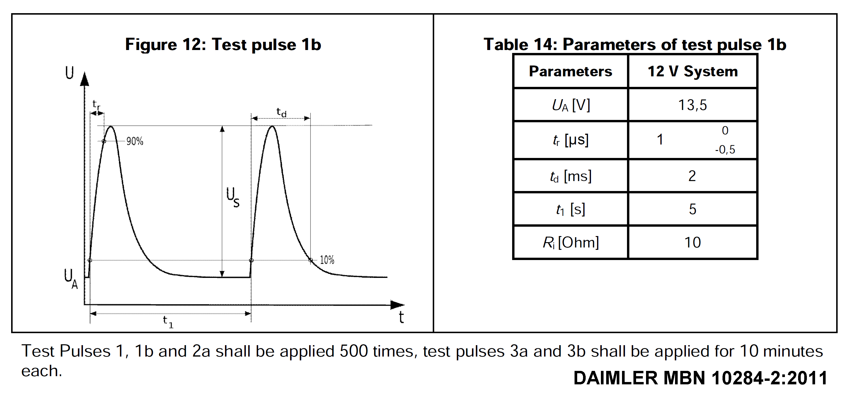
Pulse “1b” is defined differently by various international standards and/or OEM EMC specs.
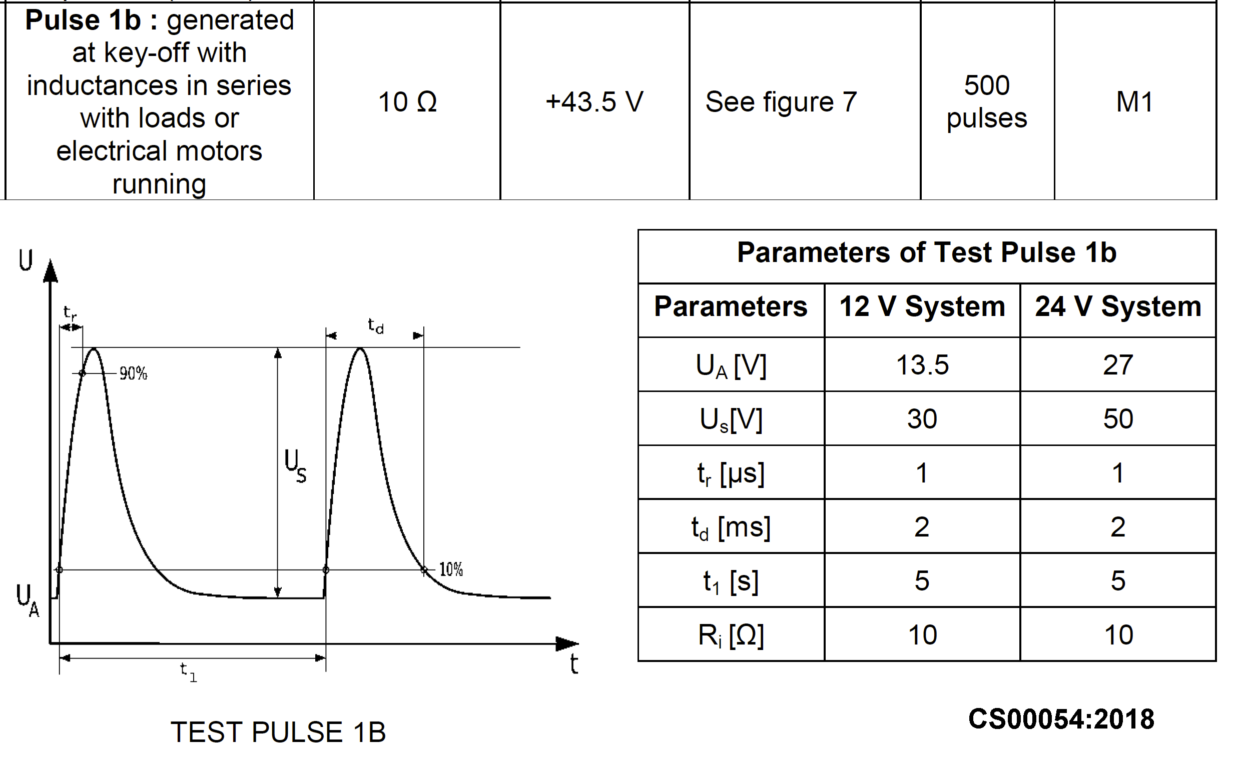
Daimler and Chrysler have quite a similar definition for Pulse 1b. Us = 30V.
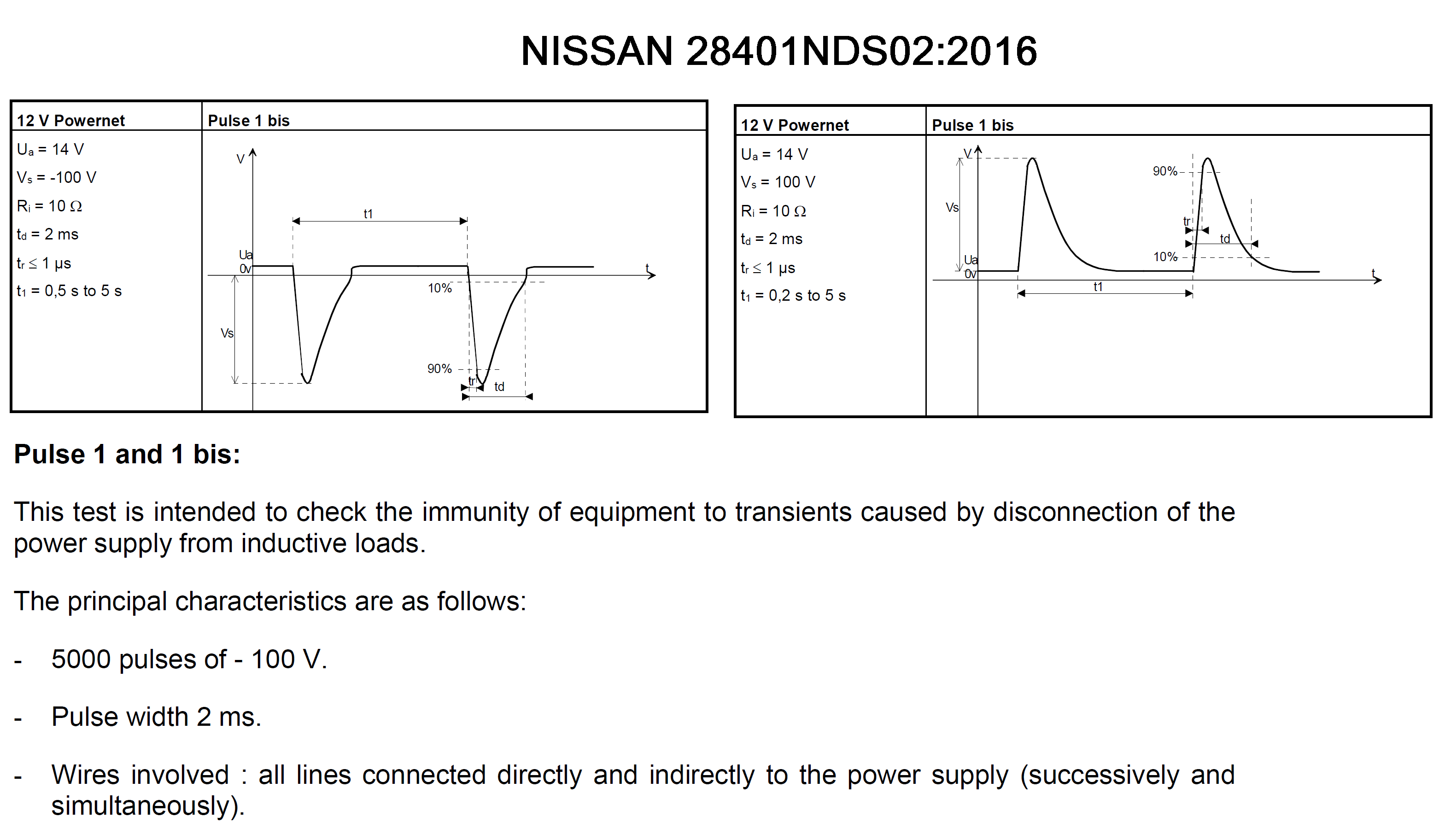
Nissan requirement for Pulse 1b is quite different (-100V).
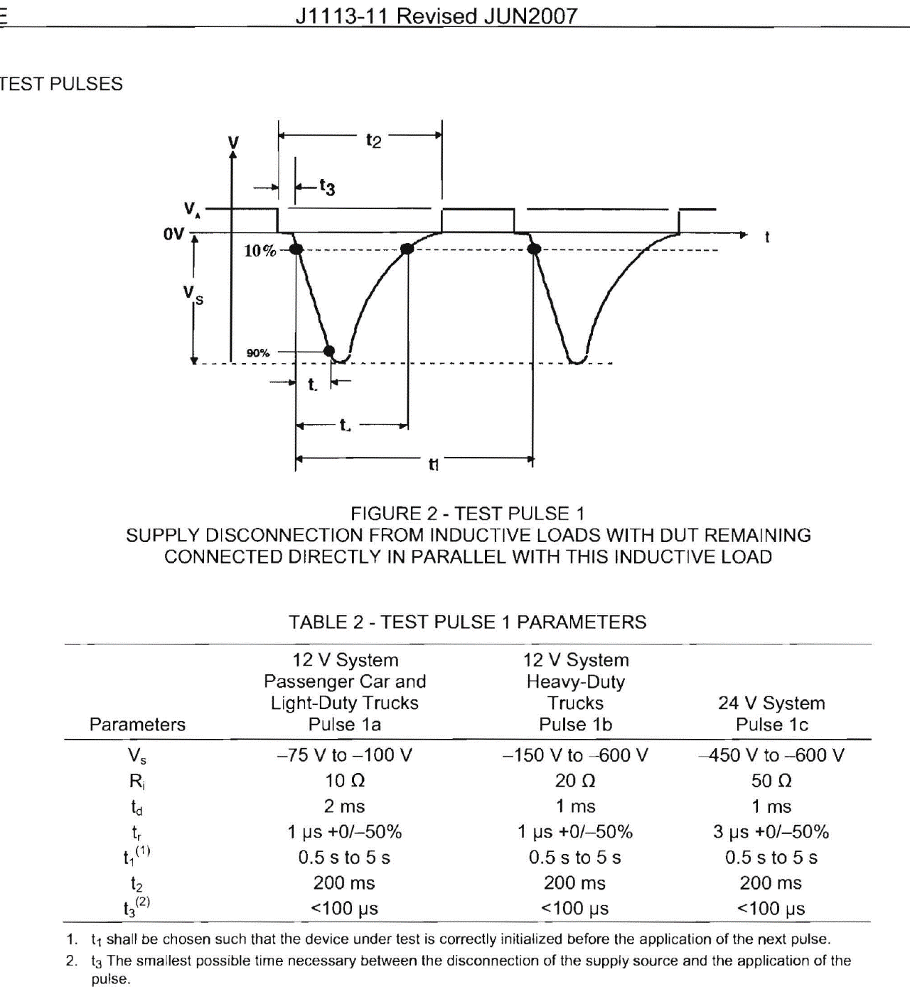
The old 2007 version of SAE J113-11 is also significantly different for multiple pulse parmeters.
Christian Rosu, 2022-01-24
FMC1278R3 specification mention that CI 280 (ESD Test Methods) must be carried out prior to any other test methods. If CI 280 fails, continuing the rest of EMC validation must be decided by FORD. The same 2 samples must theoretically withstand all FMC1278R3 test methods selected by EMC Test Plan.
The order of the test methods is critical, and the test results listed by laboratory report applies only to the two samples provided (Part Number, Serial Number, HW/SW revision). Some Europeans & Japanes automotive makers allow the use of multiple groups of samples to be used for simultaneously running test methods, probably to to speed up the completion of validation. This means that no sample is exposed to the full validation test list leaving room for insufficient EMC compliance evaluations.
Example of potentially destructive test methods:
- ESD on the first group of samples.
- Transients on supply lines on a second group of samples.
- Reverse Polarity on a third grtoup of samples
To compensate somehow such selective test methods allocation, the EMC Test Plan authors would require 3 samples per group instead of 2 samples per full validation.
A parametric test is required following each immunity test method, and this may reveal some tolerances being pushed to one extreme if not outside the acceptable range. In a real scenario, following ESD powered one unit out of three was measured with 12 KΩ impedance on B+ line versus 16 KΩ prior to test. Other than that everything was functional, the DUT current consumption was the same before and after ESD. Theoretically this unit survived ESD and based on EMC Test Plan was not supposed to be tested for Transients on Supply Lines. By mistake this unit was tested for JASO Pulse B-2 (-260V) and the outcome was "sample damged on the second pulse". This EMC test plan trick was used to hide a poor DUT design performance for Honda that otherwise would have never pass FMC1278R3 spec.

Christian Rosu, Nov 8, 2021.
ISO 7637-2 Pulse 1
Conducted Immunity to Transients on battery lines.
Pulse 1 (Us = -150V, Ri = 10Ω, td = 2 ms, tr = 1µs, t1 = ≥ 0.5s (repetition rate), t2 = 200 ms, t3 < 100µs) can upset functionality of electronic modules. Most automotive OEM specs are accepting Class B response (DUT self-recoverable deviations), others are asking Class A response (no deviations) during Pulse 1.
In this particular case the pass/fail criteria was Charging Voltage remains 5V ±0.5V for 12V Battery dropouts ≤ 500µs. The EMC test plan asked the use of DMM to monitor the USB charging function for a Class A expected response:
- This was a simulation of a mobile phone charging event.
- DMM can only detect 5V Charging Voltage dips/drops ≥ 250 µs. A FLUKE can be set to count MAX and MIN voltage peaks, otherwise to monitor 5V fast voltage fluctuations is not practically possible.
- The EMC test plan allowed the use of oscilloscope only for information.
Download this movie to see how the charging function was monitored simultaneously on both oscilloscope and DMM:
5V_Charging_during_P1.mp4 (127.57 mb)
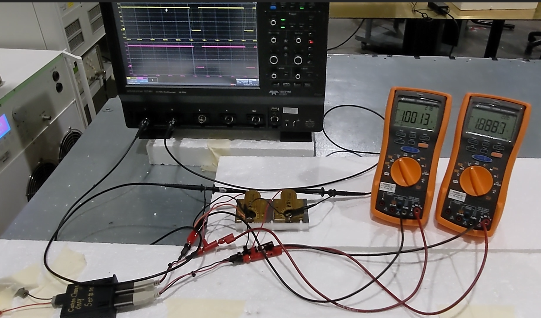
A similar monitoring equipment limitation was imposed the EMC Test Plan for dropouts test. Download this movie to see how the charging function was monitored simultaneously on both oscilloscope and DMM:
5V_Charging_during_500_microSec_dropout.mp4 (30.91 mb)
Christian Rosu, Nov 8, 2021
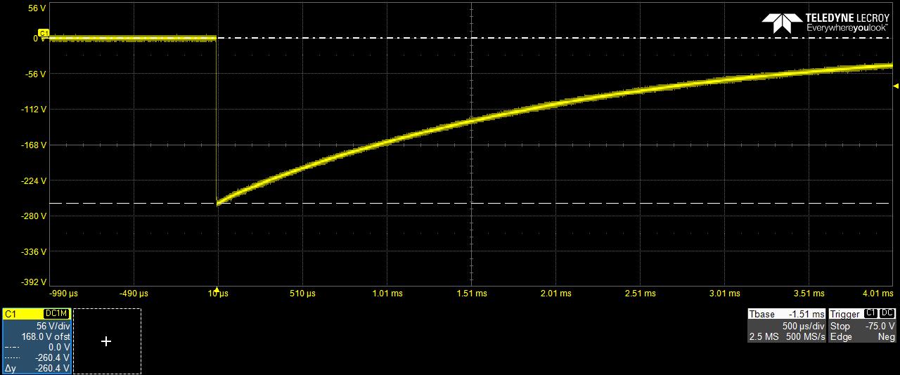
In EMC "dropout" means Battery drops to 0V. FMC1278R3 (CI 260) is an example of various combinations of such battery voltage dropouts. The problem is that no automotive battery can really drop its output to 0V for say 5 seconds as well as for 50 ms without to blowout a fuse.
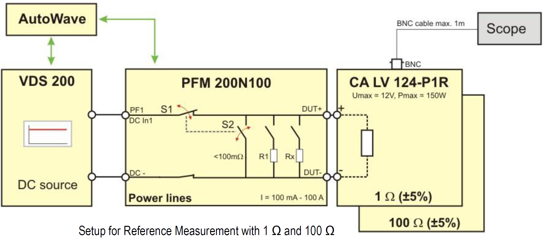
Therefore the only way to simulate correctly a “battery drop to 0V” is to disconnect DUT's B+ line from battery. The test equipment offers such capability to momentarily disconnect the battery during “voltage dropout” simulating a “0V” like condition, practically no current through supply lines to DUT.
This involves the use of PFM200N + VDS200Q + AutoWave to generate the CI 260 type of pulses. PFM200N acts like a very fast switcher disconnecting its output from DUT. So far only FCA (CS.00054) figure it out to ask “open condition” during “0V” battery voltage dropouts.
In EMC we use the wording “voltage dip” to describe a momentary battery voltage drop (e.g. 4.5V) below minimum supply voltage (e.g. 9V). Obviously in this scenario the Battery B+ line is not disconnected from DUT during the “voltage dip to 4.5V” of 100ms.
Christian Rosu Feb 17, 2021
Test Procedure:
- what the activity is (DUT type)
- who is to perform the activity (EMC Testing Laboratory)
- when the activity is to take place
This is more of an EMC Test Plan Template document that:
- defines the DUT classification and category
- lists required EMC Test Methods defined by the automotive OEM specs or International Standards (ISO, CISPR, SAE, etc.).
Test Method:
- how the actual EMC testing is to be carried out (test equipment configuration)
- defines measurable data format for reporting and acceptable stress level limits
This more of a Work Instruction outlined by automotive OEM EMC specs and international standards.
Christian Rosu, Dec 11, 2020.