The DC Power Supply should be selected as follows:
Rs (Internal Resistance) < 0.01 OHM DC
Zs (Internal Impedance) = Rs for frequencies < 400 Hz.
Output Voltage:
▶ does not deviate more than 1 V from 0 to maximum load (including inrush current)
▶ recovers 63% of its maximum excursion within 100 ms
Vr (Superimposed Ripple Voltage):
▶ does not exceed 0.2 V peak-to-peak
▶ maximum frequency of 400 Hz
NOTE:
☞ When a battery is used for EMC testing, a charging source is needed to achieve the specified voltage reference levels.
☞ It is important to ensure that the charging source does not affect the test.
☞ Linear Power Supplies are preferable vs Switching Power Supplies.
☞ Prior to CISPR 25 test methods ensure that the RF noise produced by the power supply is at least 6 dB lower than the limits specified in EMC Test Plan.
☞ If the Power Supply is located outside of the EMC test chamber, ensure thzt a bulkhead RF filter is used to prevent RF noise from entering or leaving the shielded enclosure.
☞ If using a HV battery, then it must be contained in a shielded enclosure.
☞ 12V Power Supply Volatge = 13.5 (+0.5/-1.0)V
☞ 24V Power Supply Voltage = 26 (+1.0/-2.0 V
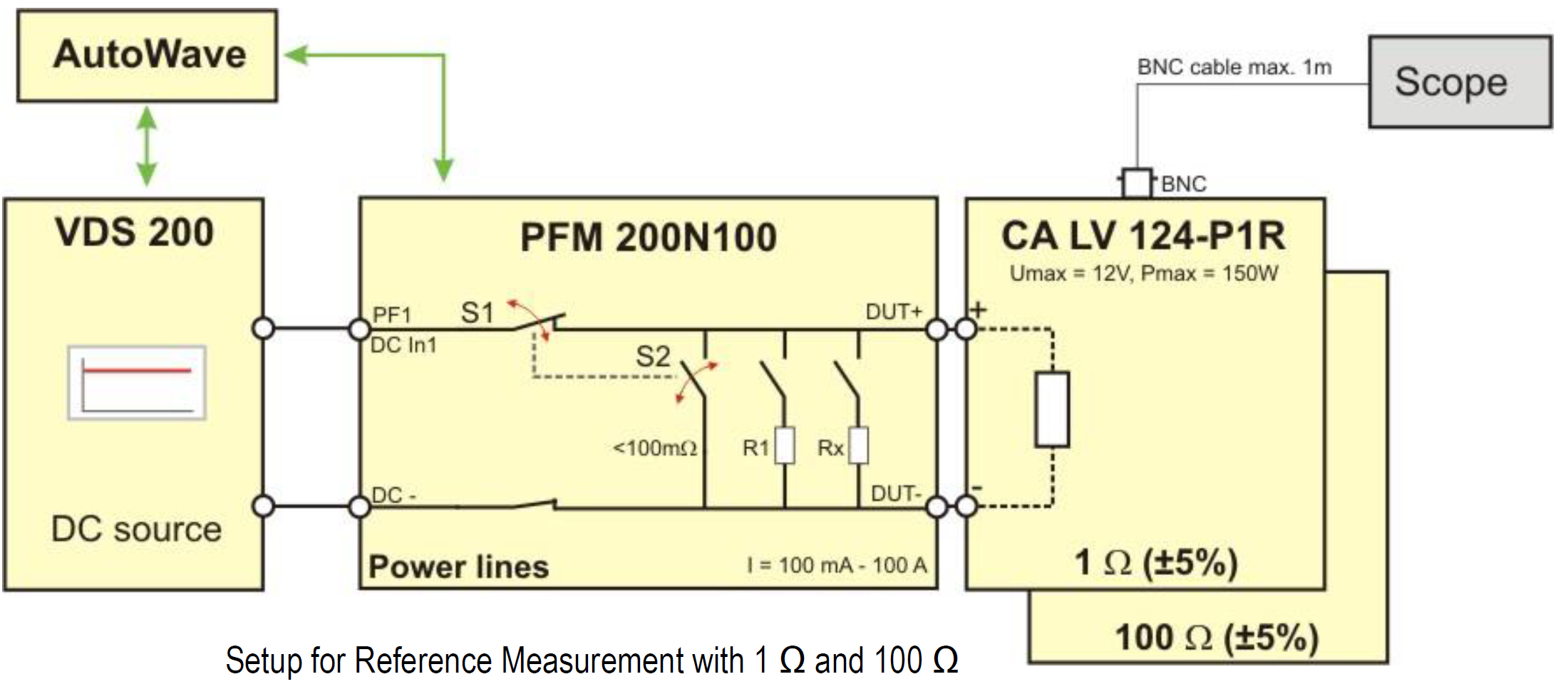
In EMC "dropout" means Battery drops to 0V. FMC1278R3 (CI 260) is an example of various combinations of such battery voltage dropouts. The problem is that no automotive battery can really drop its output to 0V for say 5 seconds as well as for 50 ms without to blowout a fuse.
Therefore the only way to simulate correctly a “battery drop to 0V” is to disconnect DUT's B+ line from battery. The test equipment offers such capability to momentarily disconnect the battery during “voltage dropout” simulating a “0V” like condition, practically no current through supply lines to DUT.
This involves the use of PFM200N + VDS200Q + AutoWave to generate the CI 260 type of pulses. PFM200N acts like a very fast switcher disconnecting its output from DUT. So far only FCA (CS.00054) figure it out to ask “open condition” during “0V” battery voltage dropouts.
In EMC we use the wording “voltage dip” to describe a momentary battery voltage drop (e.g. 4.5V) below minimum supply voltage (e.g. 9V). Obviously in this scenario the Battery B+ line is not disconnected from DUT during the “voltage dip to 4.5V” of 100ms.
Christian Rosu Feb 17, 2021
The DUT Performance Functional Verification is based on a bench test software that does not account for EMC specific considerations and is normally performed prior and following each EMC test method.
Using the same Activation & Monitoring Method and Pass/Fail Criteria for ENV and EMC is not practical. DUT’s functions must be grouped in “operating modes” that are in line with the scope of EMC Test Method. When assessing the level of RF emissions we want the DUT to exhibit the highest level of noise possible as in vehicle. During RF Immunity evaluation we expect the following from a good activation/monitoring software:
- Capability to activate and have realistic data traffic on all I/O lines as well as individual I/O lines.
- Electrical Transients or RF coupled in supply voltage and I/O lines may not always trigger repeatable anomalies. Therefore we need a visible flag/indicator to immediately stop the actual EMC test method process for anomaly thresholding (e.g. level vs frequency). As we reduce applied stress level the DUT’s behavior may change, then at some point the anomaly should disappear.
- The same DUT operating mode may be feasible for one or more EMC test methods but definitely not for the entire test list. We need capability to configure what functions belong to each operating mode including live monitoring method. Log files are not useful during test, we still need them following the test for troublesooting.
- All functions must resemble vehicle intent usage. Not all I/O lines will be active simultaneously in vehicle. Therefore do not use unrealistic I/O cables scenarios to facilitate testing since this can generate false current loops and other issues.
- The functions used by DUT activation & Monitoring Software are not meant to assess complaince to USB, E-Net, LVDS standards.
Keep in your mind that:
- Electrical Transients on supply lines can hard reset the MCU (e.g. dips/dropouts). Is there a test in your monitoring software that captures such condition? Any other anomaly is not relevant once a hard reset occurs.
- Do you have a function to verify that there is no memory loss following inadvertent hard/soft reset?
- The RF can be coupled in both supply lines and I/O lines resulting in data traffic interruptions leading to a soft reset. Is there a monitoring function to capture such event?
- If CAN bus is used in a design I would consider at minimum two critical errors: CAN BUSOFF & DTC SET. What we normally use is a pass fail criteria that can be adjusted such that is possible to determine if the anomaly occurs with every data transmission attempt or it happens only each 100/1000 attempts.
DUT support software
Do not waste time/money to tweak operating modes during EMC validations. In many EMC labs the cost for one hour of ALSE chamber is $500 regardless to how you spend this time. The operating mode must be pre-selected, yet adjustable if needed during troubleshooting. The "anomaly found" visual indicator is used by EMC test operator to stop the actual EMC test software. If we have a time stamp in log files, there is no need to stop the activation/monitoring support software.
DUT Activation Dwell Time
All functions within the same operating mode must be completed and repeated every 2 seconds. We call these 2 seconds Dwell Time, and it can make a huge difference in test duration and cost. For a 2-second dwell time and only one Operating Mode you can expect RF Immunity in ALSE chamber to last 4-5 days (one shift). For a 4-second dwell time it may last practically 8-9 days and so on. Bottom line, if the initialization of Load Simulator or DUT is time consuming it will cost a fortune to re-initialize following each incident/anomaly. Hard/soft reset must always be the last resort to resume operation. The goal is to minimize the number of operating modes and DUT orientations.
Types of DUT support software
- Load Simulator EMC support testing software with specific sections for each Operating Mode.
- Load Simulator Functional/Parametric verification testing done before and after each Test Method.
- Full DUT Functional/Parametric testing before and after full EMC validation that is not typically done using the EMC Load Simulator but rather EOL like testers.
DUT Operating Mode
Ideally is to include in Operating Modes only those DUT functions that are active while driving the vehicle. Functions used for diagnostics at the car dealer shop are not relevant. The worst case scenario is when vehicle is in Run Mode (speed >0) but we also have to simulate the Standby Mode (speed = 0) and Sleep Mode (current consumption < 1 mA).
Christian Rosu, Jan 12, 2021
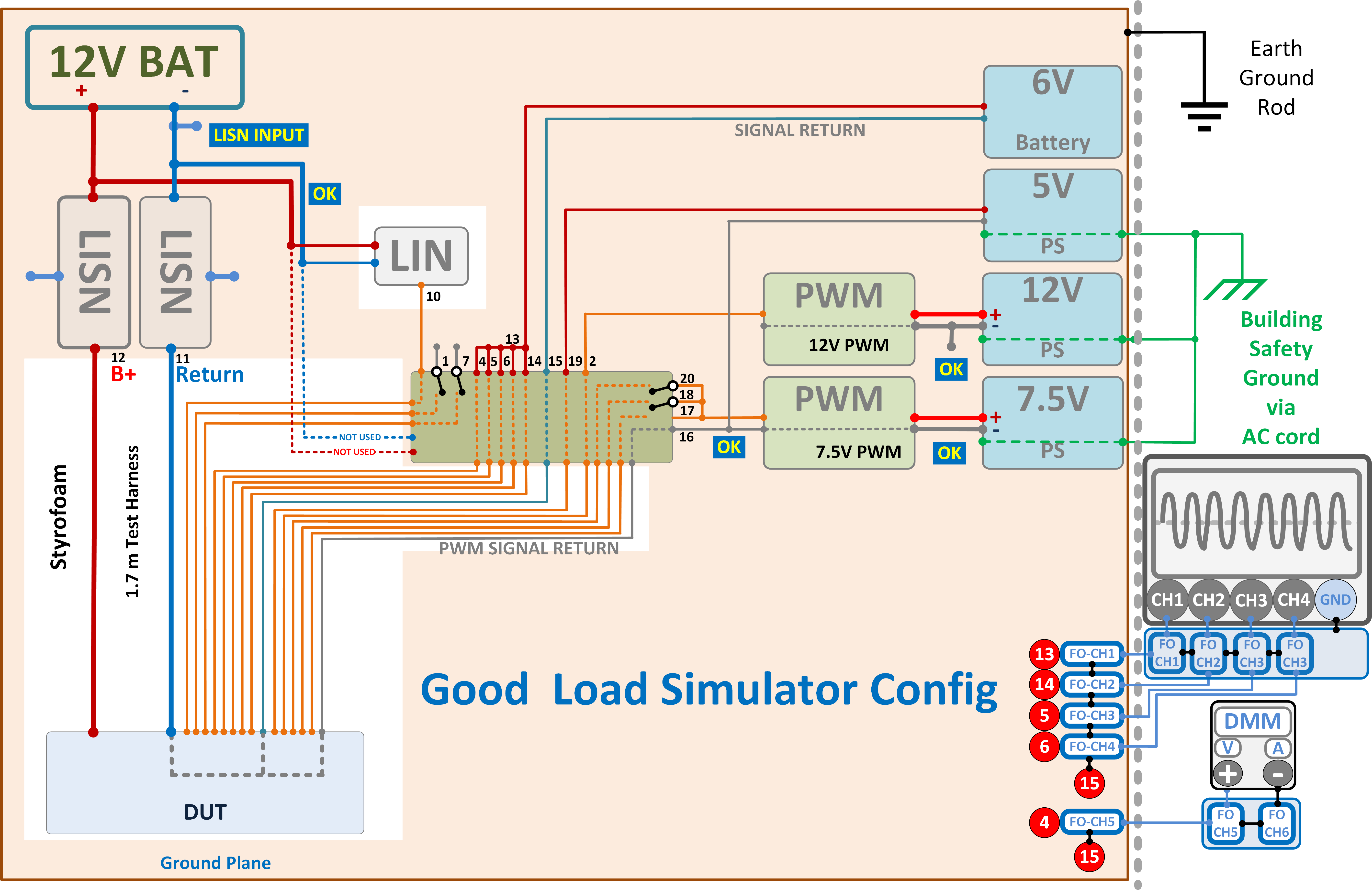
The Load Simulator must be robust and as simple as possible to become a valid reference for DUT EMC performace evaluation. The most common mistake during LS configuration for RE, BCI, RI ALSE is related to how DUT's supply return is interconected with the rest of DUT support equipment. Incorrect grounding between DUT, Load Simulator, Support Equipment, Ground Plane, dedicated Earth Grounding Rod, and Buildin Safety Ground can end up in unwanted grounding loops or as shown below to a situation where the GND LISN Input is connected to GND LISN Output.
An ideal Load Simulator is just a pass-through enclosure with test points, control switches, no active electronics. Most of the time the DUT is powered straight from the output of the B+ LISN or a Pulse Generator following certain rules in terms of B+ and GND leads length. The input of the LISN for battery negative pole is always connected to ground plane. Depending on the OEM specification or international standard used, the Load Simulator is powered directly from the automotive battery or from the output of the B+ LISN. If powered from the output of the LISN, the active electronic components part of the LS can play a role in the EMC compliance of the DUT. In automotive EMC each test bench or EMC test chamber should have dedicated Eart Grounding Rod completely separated from the Buliding Safety Ground. The incorrect grounding configuration below shows how via the test ground plane the building safety ground is in contact with the dedicated earth grounding rod. In this situation the output of the LISN is shorted to its input cancelling the purpose of the LISN.
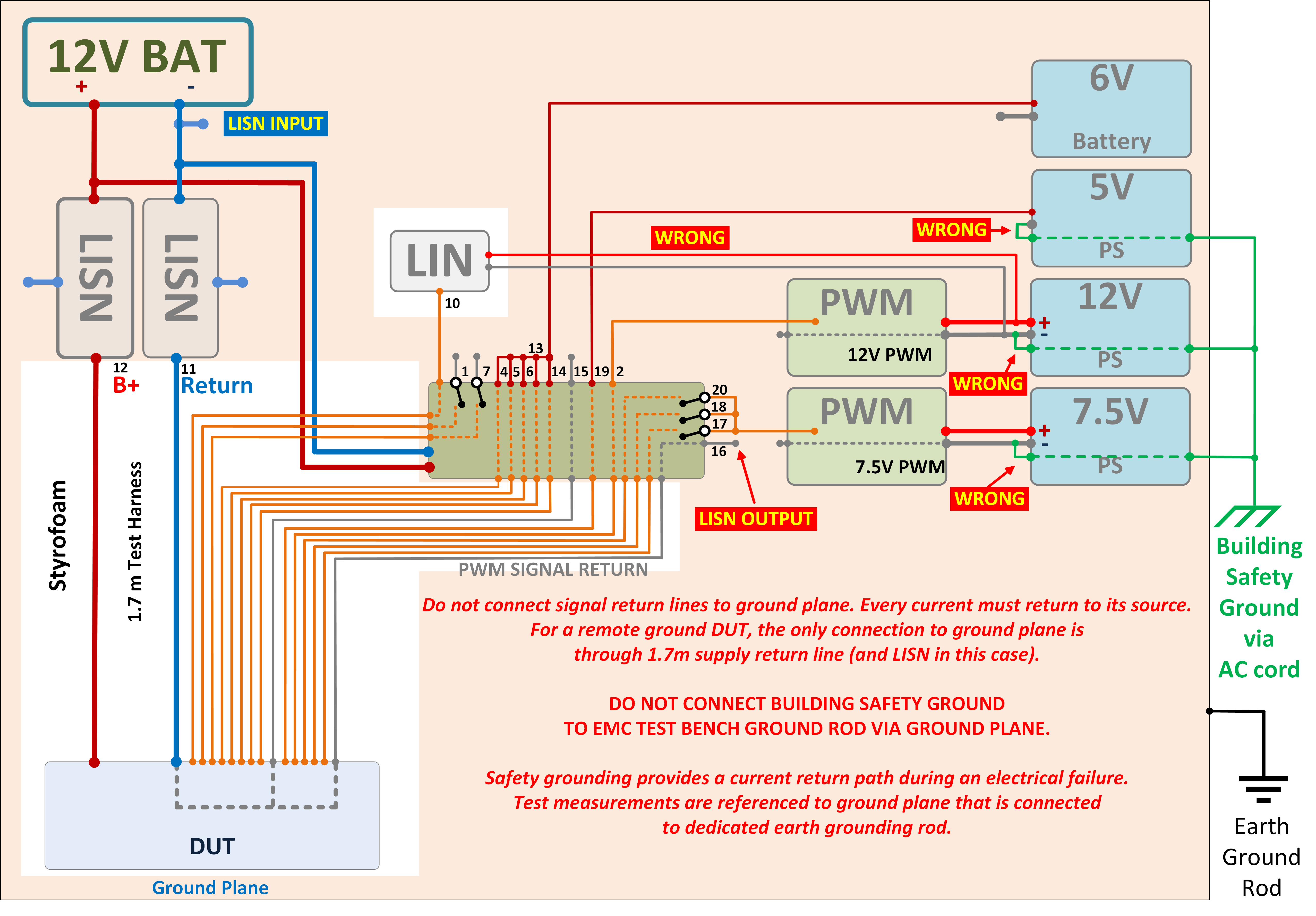
Never connect the negative terminal from support equipment power supplies to their terminal for safety ground.
2020-12-14 Christian Rosu
The automotive OEM specs do not specify how to configure the DUT during CISPR 25 chamber ambient measurements. DUT must be unpowered, all other DUT support equipment must be powered and as much as possible functional to correctly evaluate RF emissions noise floor before start testing. This leaves at least three scenarios for how to configure the DUT.
1) Disconnect the DUT from test harness.
- Test harness connectors are removed from
- DUT is unpowered.
- The 1.7 m test harness is unterminated on DUT side, no potential ground loops with Load Simulator.
- The 5uH LISN remains present.
- The Load Simulator and all support equipment remains powered.
2) Disconnect DUT's B+ line from LISN output.
- Test harness connectors are plugged into DUT.
- DUT is unpowered by disconnecting B+ line LISN input from Battery.
- The 1.7 m test harness terminated on both ends, therefore potential ground loops with Load Simulator are possible.
- The 5uH LISN remains present.
- The Load Simulator and all support equipment remains powered.
3) Diconnect DUT's B+ line from LISN output.
- Test harness connectors are plugged into DUT.
- DUT is unpowered by disconnecting DUT B+ line from LISN output.
- The 1.7 m test harness terminated on both ends, therefore potential ground loops with Load Simulator are possible.
- The 5uH LISN is not present anymore, and this somehow violates CISPR 25 requirement.
- The Load Simulator and all support equipment remains powered.
Christian Rosu