CAN bus (for controller area network) is a
vehicle bus standard designed to allow microcontrollers and devices to
communicate with each other within a vehicle without a host computer. CAN bus is a message-based protocol, designed
specifically for automotive applications but now also used in other areas such
as aerospace, maritime, industrial automation and medical equipment.
CAN bus is one of five protocols used in the OBD-II
vehicle diagnostics standard. The OBD-II standard has been mandatory for all
cars and light trucks sold in the United States since 1996, and the EOBD
standard has been mandatory for all petrol vehicles sold in the European Union
since 2001 and all diesel vehicles since 2004.
Automotive Applications
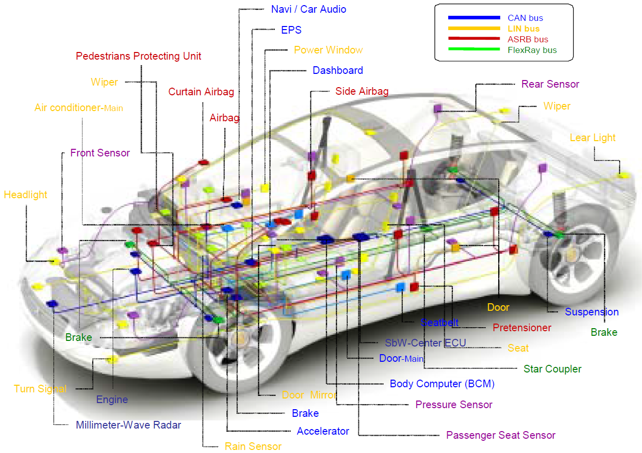
A modern automobile may have as many as 70 electronic control units (ECU) for various subsystems. Typically the biggest processor is the engine control unit (also engine control module/ECM or Powertrain Control Module/PCM in automobiles); others are used for transmission, airbags, antilock braking/ABS, cruise control, electric power steering/EPS, audio systems, windows, doors, mirror adjustment, battery and recharging systems for hybrid/electric cars, etc. Some of these form independent subsystems, but communications among others are essential. A subsystem may need to control actuators or receive feedback from sensors. The CAN standard was devised to fill this need.
The CAN bus may be used in vehicles to connect the engine control unit and transmission, or (on a different bus) to connect the door locks, climate control, seat control, etc.
Today the CAN bus is also used as a fieldbus in general automation environments, primarily due to the low cost of some CAN controllers and processors.
Bosch holds patents on the technology, and manufacturers of CAN-compatible microprocessors pay license fees to Bosch, which are normally passed on to the customer in the price of the chip. Manufacturers of products with custom ASICs or FPGAs containing CAN-compatible modules may need to pay a fee for the CAN Protocol License.
Technology
CAN is a multi-master broadcast serial bus standard for connecting electronic control units (ECUs). Each node is able to send and receive messages, but not simultaneously. A message consists primarily of an ID (identifier), which represents the priority of the message, and up to eight data bytes. The improved CAN (CAN FD) extends the length of the data section to up to 64 bytes per frame. It is transmitted serially onto the bus. This signal pattern is encoded in non-return-to-zero (NRZ) and is sensed by all nodes.
The devices that are connected by a CAN network are typically sensors, actuators, and other control devices. These devices are not connected directly to the bus, but through a host processor and a CAN controller. If the bus is idle which is represented by recessive level (TTL=5V), any node may begin to transmit. If two or more nodes begin sending messages at the same time, the message with the more dominant ID (which has more dominant bits, i.e., zeroes) will overwrite other nodes' less dominant IDs, so that eventually (after this arbitration on the ID) only the dominant message remains and is received by all nodes. This mechanism is referred to as priority based bus arbitration. Messages with numerically smaller values of IDs have higher priority and are transmitted first.
Each node requires:
Host processor
• The host processor decides what received messages mean and which messages it wants to transmit itself.
• Sensors, actuators and control devices can be connected to the host processor.
CAN controller (hardware with a synchronous clock).
• Receiving: the CAN controller stores received bits serially from the bus until an entire message is available, which can then be fetched by the host processor (usually after the CAN controller has triggered an interrupt).
• Sending: the host processor stores it’s transmit messages to a CAN controller, which transmits the bits serially onto the bus.
Transceiver
• Receiving: it adapts signal levels from the bus to levels that the CAN controller expects and has protective circuitry that protects the CAN controller.
• Transmitting: it converts the transmit-bit signal received from the CAN controller into a signal that is sent onto the bus.
Bit rates up to 1 Mbit/s are possible at network lengths below 40 m. Decreasing the bit rate allows longer network distances (e.g., 500 m at 125 kbit/s). The improved CAN (CAN FD) extends the speed of the data section by a factor of up to 8 of the arbitration bit rate.
The CAN data link layer protocol is standardized in ISO 11898-1. This standard describes mainly the data link layer (composed of the logical link control (LLC) sublayer and the media access control (MAC) sublayer) and some aspects of the physical layer of the OSI reference model. All the other protocol layers are the network designer's choice.
Sources: Bosch
Christian Rosu